Lightning rods on general buildings can only prevent direct lightning strikes, but induced lightning and pulse voltages generated by powerful electromagnetic fields can sneak into the room and endanger electrical equipment such as televisions, telephones, and electronic instruments. The most common harm to electronic equipment is not caused by direct lightning strikes, but by the surge voltage that can flow in from power lines or signal lines when a lightning strike occurs.
Lightning strike induction
Short circuit fault occurs in the power system
Power surges occur when switching large loads
The intricate and long power grid system
Our company is located in the Wuyi Mountains experimental base in Fujian, southern China, close to Jiangxi, and measures the surge voltage that occurs between low-voltage distribution lines (220V) in general residences and other low-voltage distribution lines (220V) that exceeds twice the original operating voltage within 8000 hours (about 365 days). The number of surges reached more than 700 times, including more than 300 surges exceeding 1000V.
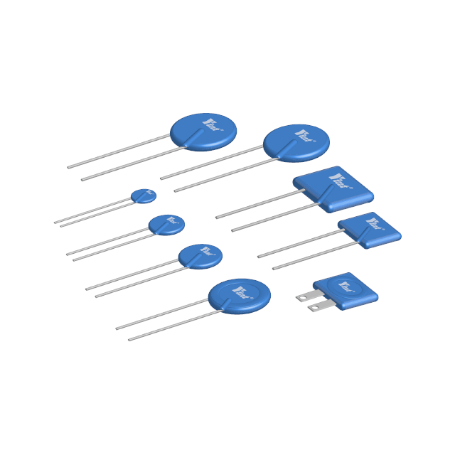
In view of the above situation, Yint Electronics mainly considers the common phenomenon of current power supplies not being grounded, and designs a single-phase parallel anti-lightning surge circuit based on varistor and ceramic gas discharge tube, and applies it to the switching power supply of instruments. It is a circuit that can meet the differential mode test standards of the national standard GB/T17626.5, but is indeed more effective in actual use.

It mainly explains the lightning protection circuit part. The circuit is simple, using differential mode two-level full protection, and can be connected regardless of the L and N terminals.
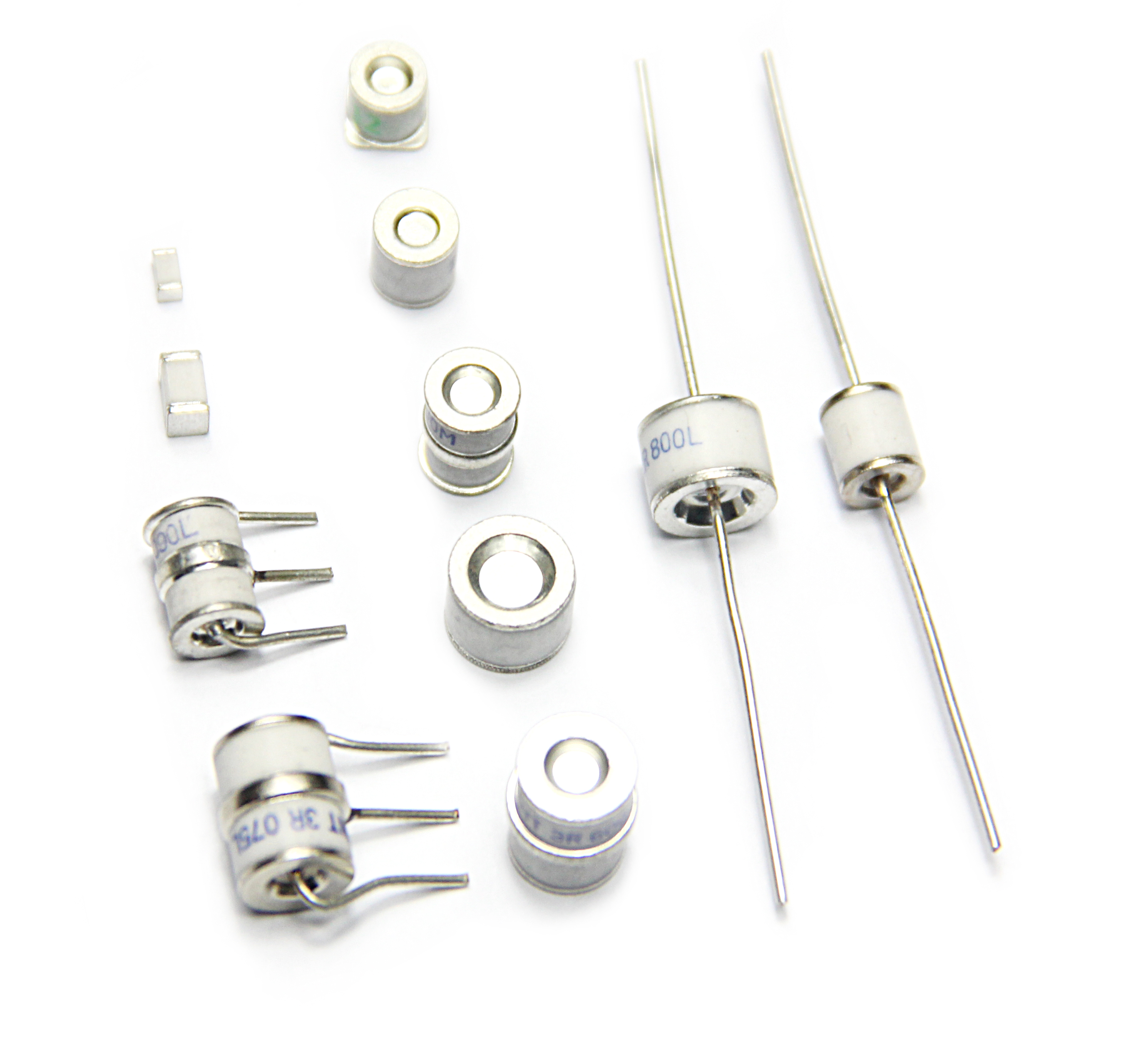
Use the varistor MOV1 and the gas discharge tube GDT1 as the first-stage parallel connection on L and N. The connection mode of L and N can be ignored. When a large surge current comes, the circuit has no discharge channel, so the varistor It absorbs the clamping and allows a large part of the current to be discharged in the form of an arc inside the gas discharge tube. In addition, using MOV1 and GDT1 in parallel mode can solve the circuit short circuit caused by the freewheeling problem of the gas discharge tube.
Use MOV2 before the rectifier or filter circuit, mainly to clamp the voltage between L and N lines
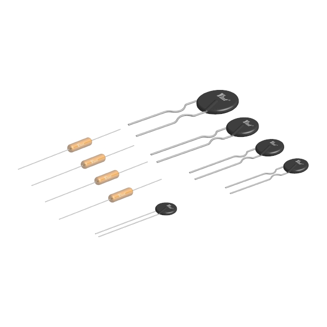
The NTC power thermistor is connected in series because it can effectively suppress the surge current when starting up. And after the surge current suppression is completed, due to the continuous action of the current passing through it, the resistance value of the power NTC thermistor will be Down to a very small level, the power it consumes is negligible and will not affect the normal operating current. Therefore, using a power NTC thermistor in the power supply circuit is the simplest and most effective measure to suppress surges during startup and ensure that electronic equipment is protected from damage.
When MOV2 fails due to short circuit, the thermistor can play a current limiting role. When the energy exceeds its own ability to work, the thermistor can also be directly disconnected, thus cutting off the circuit.
Mainly related standards: IEC6100-4-5 / GB/T17626.5 comprehensive wave 8/20US 1.25/50US low power supply impedance, use equivalent input 2Ω.
A total of five categories of requirements: Category I: 0.5KV, Category II: 1KV, Category III: 2KV, Category IV: 4KV, Category V: 10KV or 100KV (mountainous area or Dolei forest area)
Category I :0.5KV | MOV1 | GDT1 | MOV2 | NTC1 |
Device model |
*The thermistor can calculate the R25 resistance and the corresponding operating steady-state current based on the circuit heat capacity alone.
Category II:1KV | MOV1 | GDT1 | MOV2 | NTC1 |
Device model |
*The thermistor can calculate the R25 resistance and the corresponding operating steady-state current based on the circuit heat capacity alone.
Category III:2KV | MOV1 | GDT1 | MOV2 | NTC1 |
Device model |
*The thermistor can calculate the R25 resistance and the corresponding operating steady-state current based on the circuit heat capacity alone.
Category IV:4KV | MOV1 | GDT1 | MOV2 | NTC1 |
Device model |
*The thermistor can calculate the R25 resistance and the corresponding operating steady-state current based on the circuit heat capacity alone.
Category IV:10KV | MOV1 | GDT1 | MOV2 | NTC1 |
Device model |
Special note:
The above device selection is for general circuit design. If the circuit design PCB engineer is experienced, he or she may consider appropriately reducing the device model.