Views: 0 Author: Site Editor Publish Time: 2023-10-24 Origin: Site


As a recognized green lighting product, electronic ballast fluorescent lamps have many obvious advantages over ordinary inductive ballast fluorescent lamps, such as high luminous efficiency, no flicker, and significant energy saving effects; however, some electronic ballasts also have higher failure rates. Disadvantages: For end customers, electronic ballasts have become a high-cost (relative to inductive ballasts) disposable products.
Through our research, we found that one of the main reasons for the above problems is that some electronic ballast manufacturers did not take reliable protection measures against the abnormal status of the electronic ballast for various reasons, causing the electronic ballast to follow the lamp. scrapped at the end of its life.
We know that the general electronic ballast design scheme and related basic principles are as shown in the following figure:

This high voltage causes arc discharge of the fluorescent lamp and starts the fluorescent lamp, then the resonant circuit is detuned and the fluorescent lamp enters a stable ignition state.
When abnormal conditions such as lamp aging or lamp leakage occur, the fluorescent lamp cannot start normally, and the above circuit is always in a resonant state (unless the filament is burned out or the electronic ballast is damaged), and the current output by the inverter continues to increase. Usually this current will increase to 3 to 5 times the normal current. If effective protective measures are not taken at this time, great harm will be caused. First of all, excessive current will cause the triode or field effect transistor and other peripheral components used as switches in the inverter to burn out due to overload, and even cause accidents such as smoke and explosion. At the same time, the lamp pin will form an extremely high voltage to the ground or neutral line for a long time. For electronic ballasts of 20W, 36W, 40W and most other national standard/non-standard lamps, this voltage often reaches one thousand volts or more. High, this is not only strictly prohibited by the national standard GB15143, but also endangers personal and property safety. The abnormal state tests for electronic rectifiers in GB15143-94 "11, 14" and GB15144-94 "5.13" include: lamp open circuit, cathode damage, deactivation, rectification effect, etc., and it is also stipulated that electronic ballasts shall not be used after the above tests. A security failure occurs and functions normally.
At present, electronic ballasts use more protection measures, including the following:
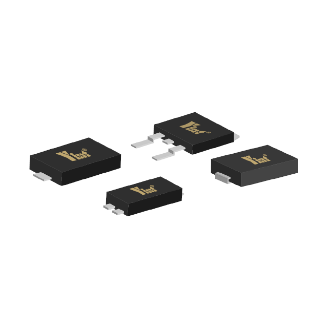
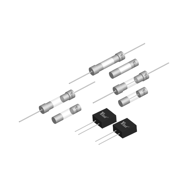
1. Connect a glass tube fuse in series to the AC input circuit. Connecting a fuse in series at this position may cause some people to mistakenly think that it will play a role in overcurrent or overload protection; in fact, such a protection method generally does not provide protection under overload conditions such as filament deactivation. It is often used in switching devices. It will fuse only after breakdown, and it cannot play a real protective role in abnormal conditions.
2. Use a protection circuit with thyristor, bipolar transistor or field effect transistor as the core on the rectifier output circuit. The biggest advantage of this electronic circuit protection method is that the protection time is short, but it also has the following disadvantages:
False protection is prone to occur: If for some reason, even a very short sharp pulse is formed at the trigger end of the thyristor, it will cause the inverter to stop working, causing the light to go out.
The design and debugging work is relatively cumbersome: Under normal circumstances, this kind of protection circuit will have at least 6 electronic components including resistors, capacitors, and pulse transformer secondary coils. So many components plus thyristors, etc. are used at the same time. Problems such as discreteness and temperature drift of active devices will increase the difficulty of debugging, thereby affecting production efficiency.
This protection method also has the disadvantages of higher cost and larger PCB space occupation, which is also a headache for many electronic ballast manufacturers.
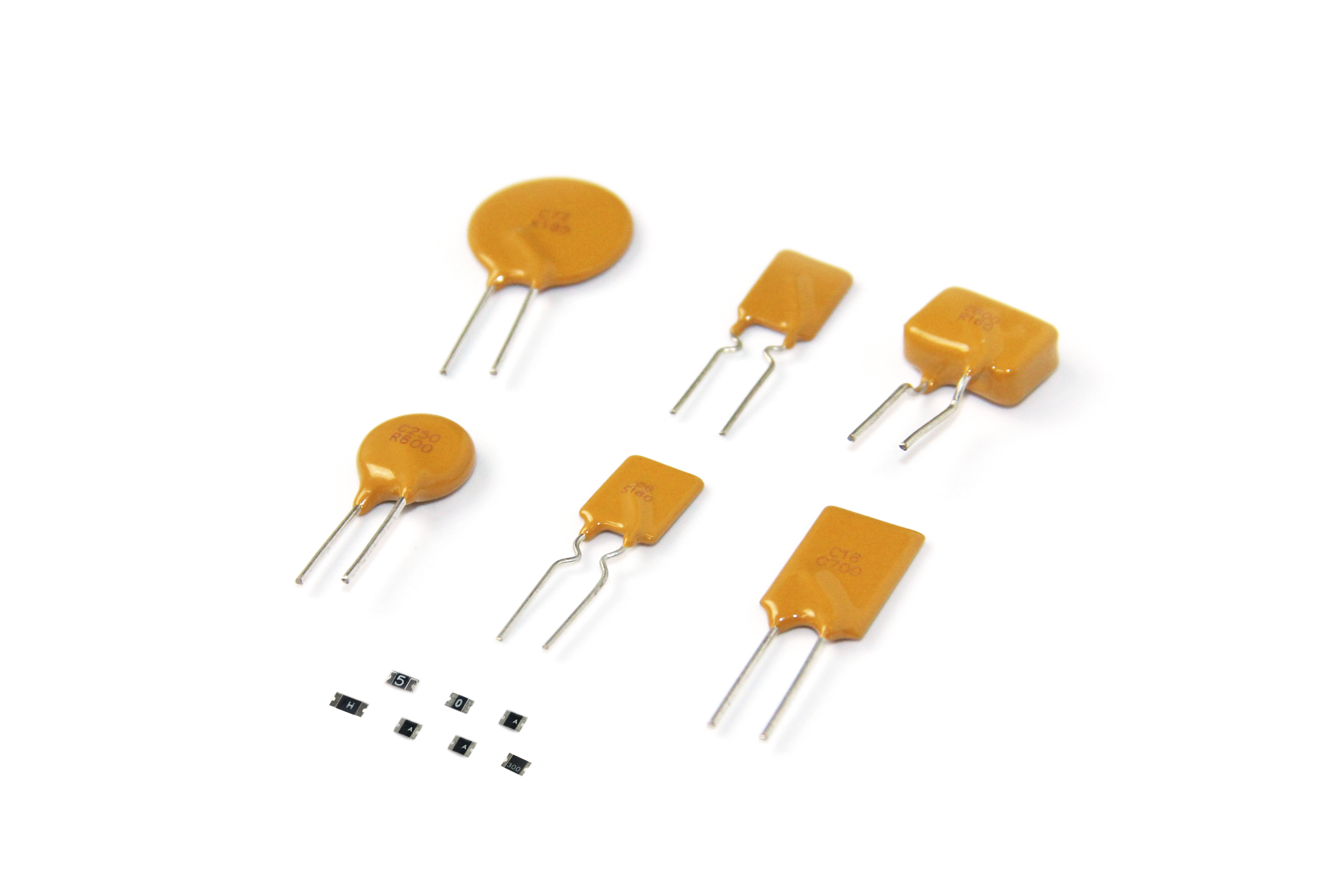
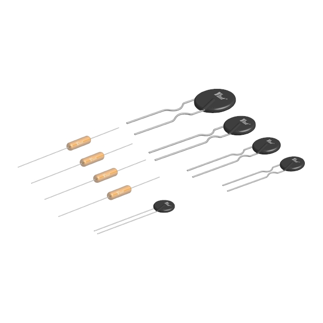
3. Connect a self-restoring polymer PTC thermistor in series next to the resonant circuit, that is, the resonant capacitor. Figure 2 is a circuit schematic diagram that uses polymer PTC thermistor to implement abnormal protection for electronic ballasts.
When the lamp is normal and the electronic ballast is powered on, the resonant circuit composed of the inductor, capacitor and PTC thermistor causes the fluorescent lamp to start working normally. If the lamp is deactivated due to filament aging or air leakage, the PTC thermistor will act within a few seconds, forcing the LC series resonant circuit to stop oscillating, thereby cutting off the high voltage and protecting the switching devices in the inverter.

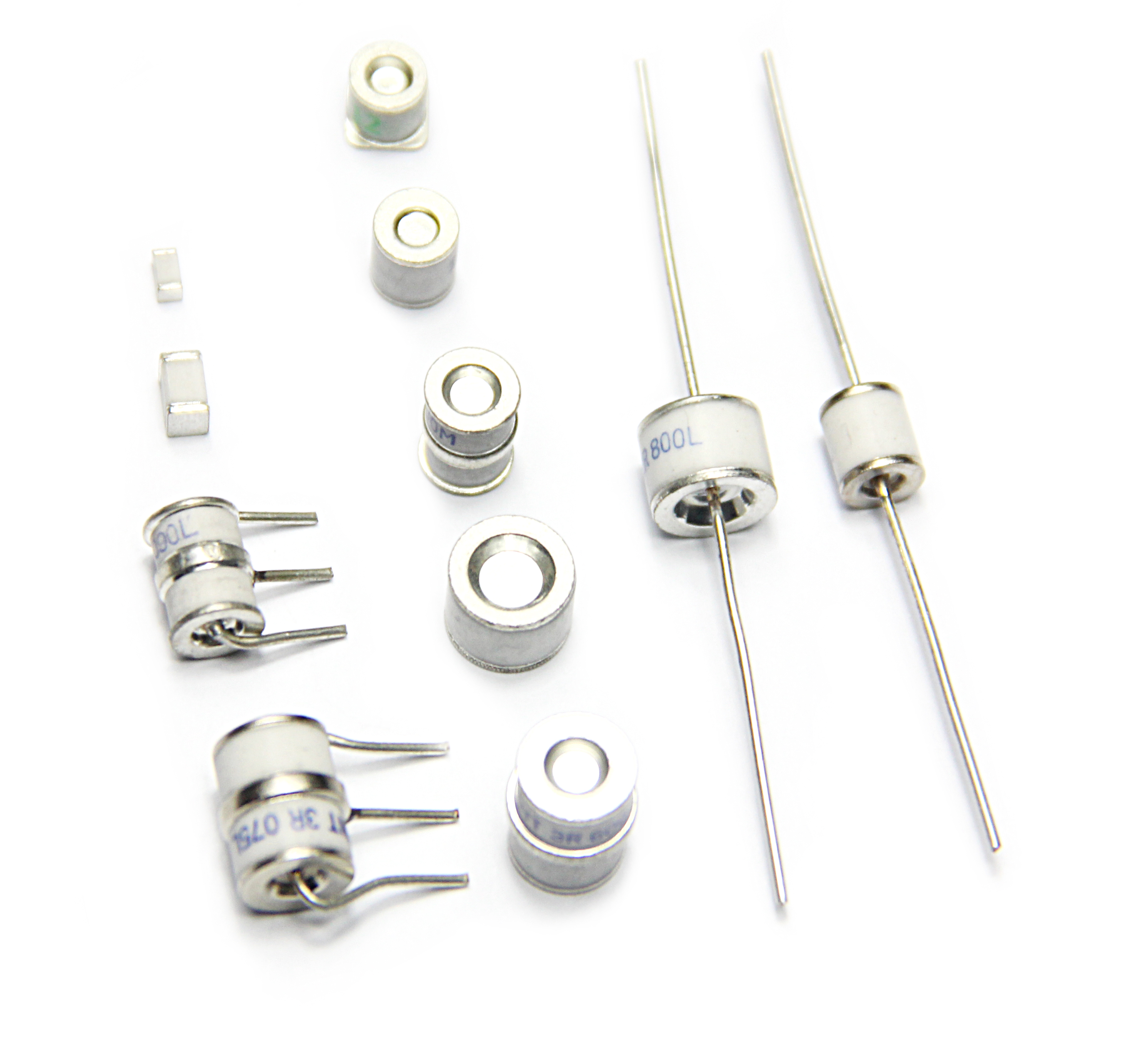
The advantages of this protection method have been recognized by many electronic ballast manufacturers. Our company has developed the R250 series of PTC thermistors specifically for electronic ballasts, which can also ensure good protection characteristics at room temperature. In addition, On the one hand, PTC maintains very stable performance even after multiple or extended periods of protection.
4. Application of R250 series PTC in double lamp/multiple lamp electronic ballast:
Usually, with electronic circuit protection methods such as thyristors, when one of the dual/multiple lamps is deactivated, it will cause the entire ballast to stop working, causing even normal fluorescent lamps to go out at the same time, which is often disturbing. of. The use of PPTC thermistors solves this problem. We can make an explanation through the following circuit.

In the above figure, assuming that fluorescent lamp 1 is deactivated, PTC1 operates, and the filament current of lamp 1 is close to 0; but the operation of other fluorescent lamps will not be affected. In this way, users do not have to worry about which lamp has reached the end of its life or the ballast is damaged.
From the above application examples, we can know that PPTC series thermistors have the following obvious advantages:
It is convenient for manufacturers to simplify circuit design, especially to provide a simpler and more reliable design solution for dual-light and multi-light protection.
Reduce the cumbersomeness of debugging and assembly, which will help improve production efficiency.
It has good, comprehensive and stable high and low temperature performance.
Reduce costs and save PCB space.
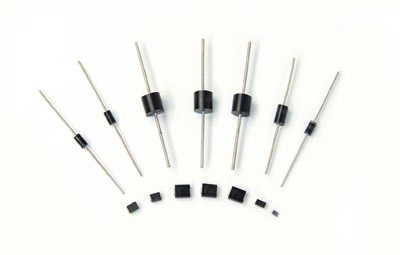
This series of resettable fuses can be applied to various national standard/non-standard straight tube fluorescent lamps, ring fluorescent lamps and U-shaped lamps, etc.
Thermistor (PTCR) is used in electronic ballasts and energy-saving lamps as preheating soft start, which can greatly increase the number of switching times and service life of the lamp.