As one of the most commonly used serial differential communication methods in the industry at present, RS485 adopts the method of balanced transmission and differential reception, so it has the ability to suppress common mode interference, because of its long communication distance (above 1200m) and high transmission rate (10Mbps), high signal-to-noise ratio, convenient control, low cost, multiple nodes can be realized on a single bus, and there are many types of transceivers that can be used, etc., which have been more and more affirmed by users.
However, with the increase of the frequency of use, the problems encountered are also increasing. Since the RS485 communication transmission line is usually exposed outdoors, lightning and static interference in daily life have become problems that the RS485 communication bus often encounters in practical engineering. The working voltage of the RS485 transceiver is low, only 5V, the withstand voltage of the components themselves is also low, usually only -7V ~ +12V, so the overvoltage introduced by lightning can usually damage the RS485 transceiver instantly, causing serious damage to the communication system; in addition, static electromagnetic interference It also seriously affects the data transmission quality of the communication bus.

Features: This scheme is a two-level protection. The first level uses a gas discharge tube for coarse protection, the second level uses TVS for fine protection, and the recoverable fuse PPTC is used for current-limiting coupling between the two levels, also known as two-level coordination.
Device selection
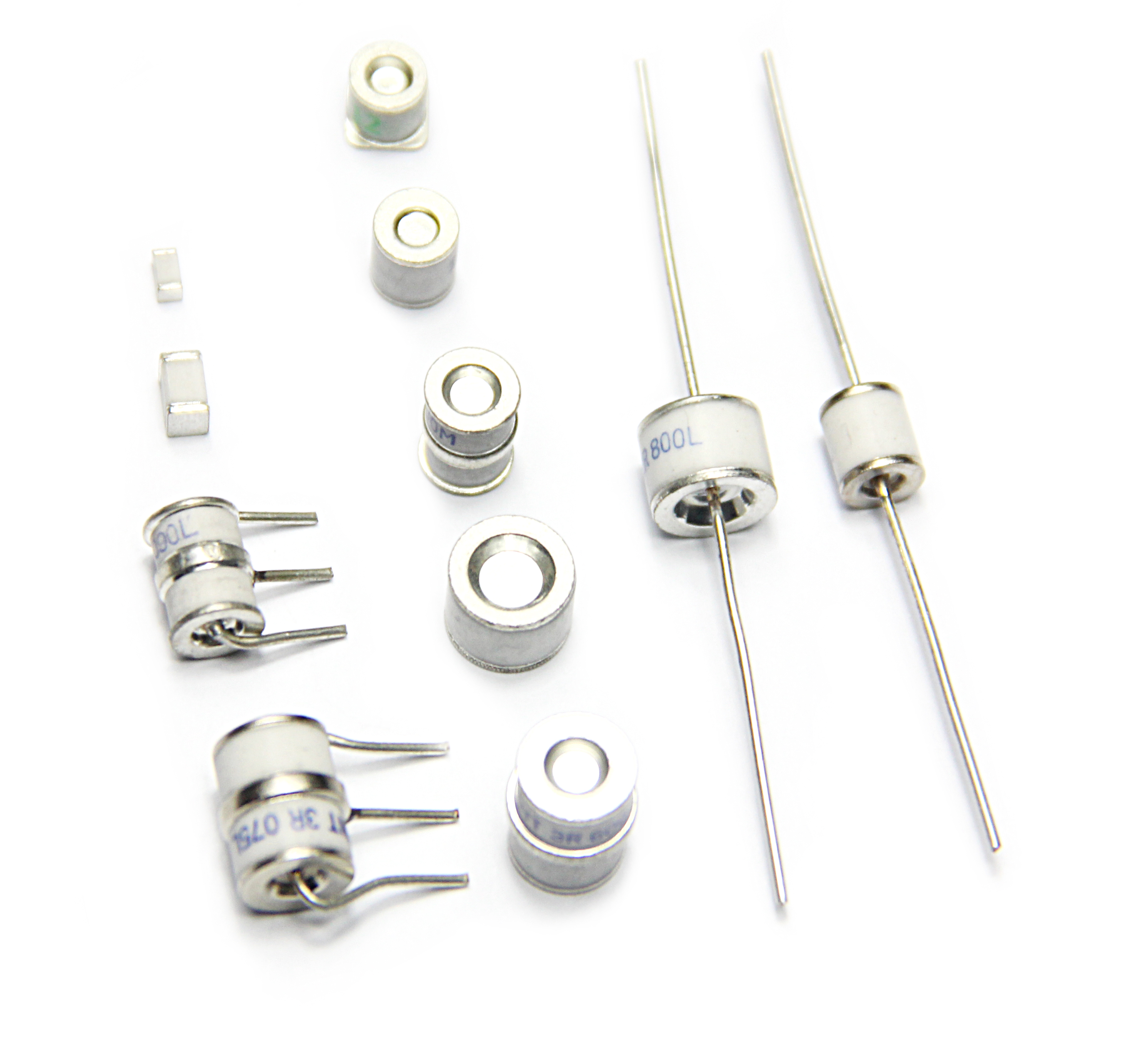
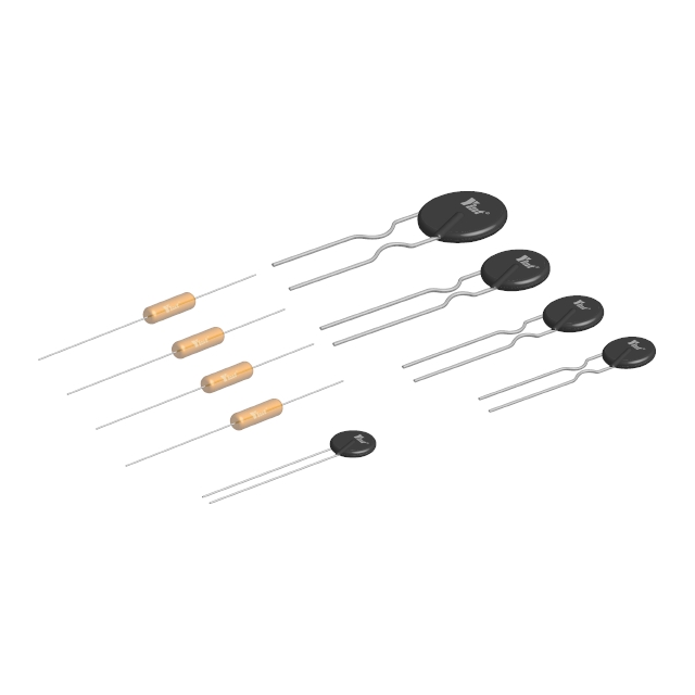
GDT: 3R090M (SMD) 3R090R (Plug-in)
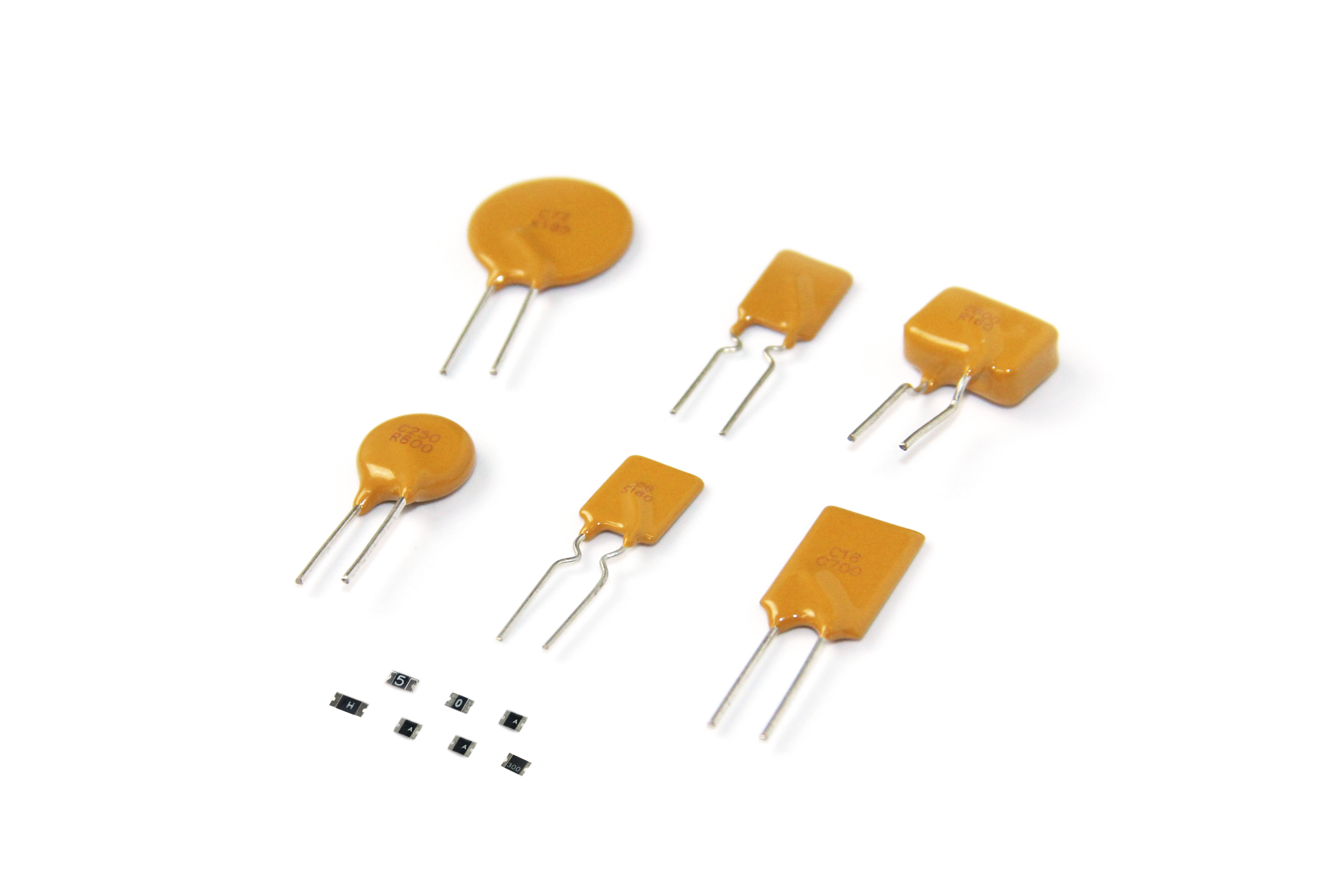
PPTC: SMD1206-010, 250V-120, R, L can also be used instead, please contact Yinte Electronics for details.
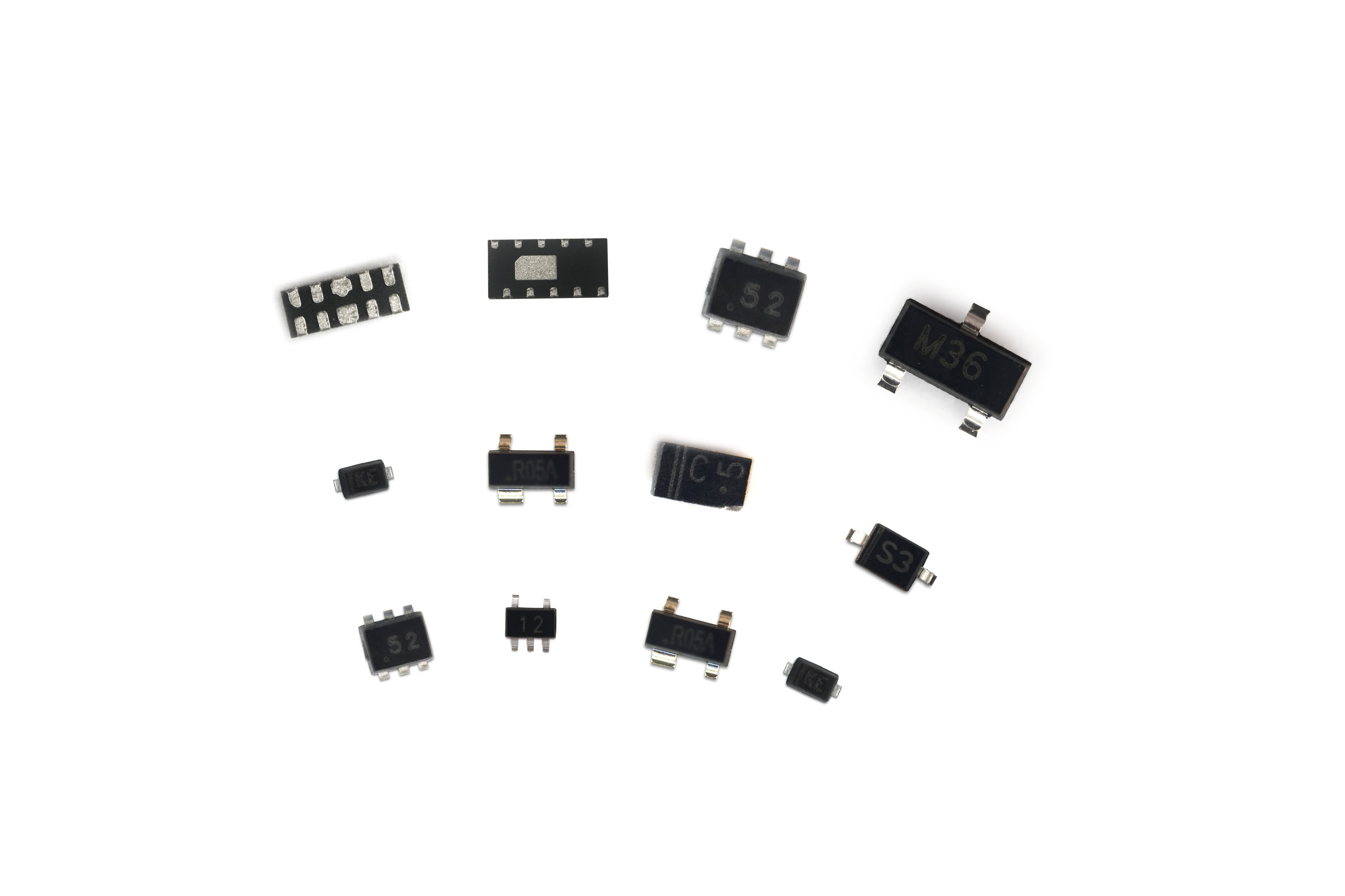
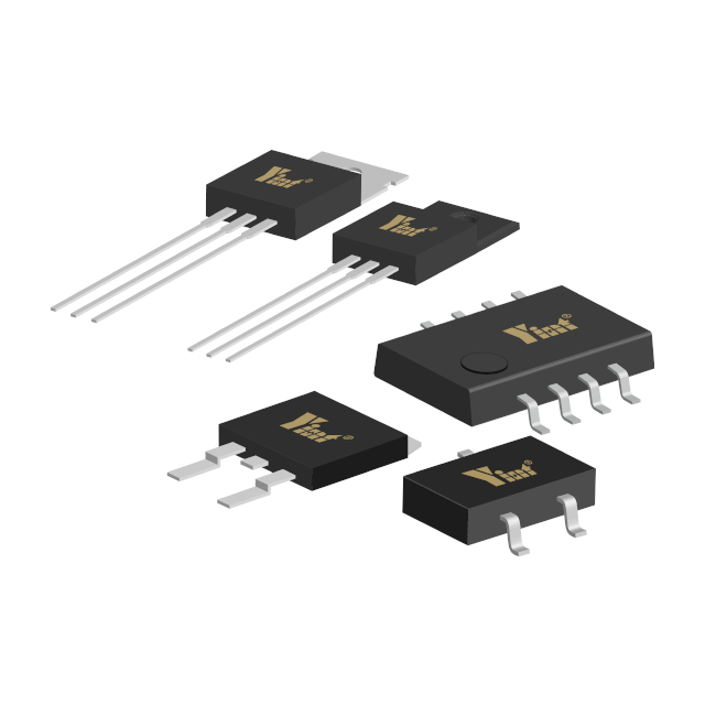
TVS1: SMBJ6.5CA P6KE7.5CA #1
TVS2 3: SMBJ6.5CA P6KE7.5CA #2
#1 Note: TVS1 is used for differential mode protection. Generally, the voltage difference between the two RS485 lines is ± (2~6) V, which can be adjusted according to the specific situation of the customer. For details, please contact Shanghai Yinte Electronics.
The common mode voltage range of #2RS-485 transceiver is -7~+12V.
Some precautions for the solution: the parasitic capacitance of the gas discharge tube is very low, 2pf, but the general type of TVS parasitic capacitance is more than 100pf, which has a certain impact on the high-speed transmission of the signal, and needs to be paid attention to during design.In addition, if there is no reliable grounding, this solution needs to be adjusted (signal ground, ground connection readjustment), please contact Yinte Electronics for details.
Scenario 2

Compared with scheme 1, scheme 2 only replaces TVS with semiconductor discharge tube TSS, which is characterized by low parasitic capacitance and larger flow rate than 600W TVS.
Scenario 3

The secondary protection of this scheme uses the ESDSM712 chip specially designed by Yinte for RS485ESD. The off voltage of PIN1,2to PIN3 of this chip is 12V, and the off voltage of PIN3To PIN1,2 is asymmetrical design of 7V, which meets IEC 61000-4- 2 (ESD): Air 15KV, Contact 8KV. And its parasitic capacitance is also very small, which meets the requirements of high-speed transmission.
In addition, considering that the protection circuit may have to withstand huge surge energy, special considerations must be made in the layout and wiring, such as sensitive signals, devices should be kept away from the protection circuit, the grounding line of the protection device should be as short as possible, and the line width of the path between the protection devices be enough, keeping sufficient creepage distance, and when using ground isolation protection, try to avoid signals from crossing two different ground systems, etc.
The above three protection schemes are commonly used protection schemes. If customers are limited by some factors, such as small product size, low protection level, etc., other schemes can be designed to meet customer needs.