Views: 0 Author: Site Editor Publish Time: 2021-07-27 Origin: Site


Electricity, gas, water, and heating bills are closely related to everyone's lives, and the disadvantages of manual meter reading, such as long time, low efficiency, inaccurate statistics and high staff costs, are very obvious. If you take into account time-of-use billing such as step tariffs and time-of-use tariffs, as well as power quality (PQ) detection and real-time fault alarms, it is completely impossible to complete manual meter reading.
With the advancement of science and technology, driven by industry associations and major companies, coupled with macro-control at the nationallevel, the remote centralized meter reading system has gradually become mature and shaped solutions, and being promoted to both at home and abroad.
YINT also takes full advantages of its own technology and resources in protection devices, and plays an important role in the remote centralized meter reading system. It comprehensively designs circuit protection solutions for a more optimized and secure remote centralized meter reading system, for the design reference of smart meter AMR, collector and centralizer design engineers.

The Concentrated Metering System is generally composed of four levels: terminal smart meters (water, electricity, gas and heat), collector, concentrator, and back-end master station, as shown in the figure below.
The terminal smart meter, Smart Meter, is the most grounded, closest to the user, even into the household metering, such as smart meters, water meters, gas meters, and heat meters for heating in the northern areas.

Figure 2 Sample diagram of smart electricity, gas, water and heat meters (image source online)
The main function of the smart terminal meter is to carry out terminal metering and fee control management, collecting information from the user terminal on the use of electricity, water, gas and heat and displaying feedback related information to the user, such as usage, current step price, precharged balance, etc. .

The information collected from the user terminal needs to be uploaded in real time (or in sections) from the collector to the server backend, and the management backend also needs to issue relevant fee control or security authentication management instructions, therefore, the smart terminal meter also integrates a communication module, and the common terminal meter adopts communication methods such as RS485, power carrier and infrared. As shown in Figure 3, the block diagram of the composition of the smart meter.
YINT has designed reliable and complete circuit protection solutions for the power management and communication circuits of smart electricity meters, smart water meters, smart gas meters and smart heat meters, and has related test data under various test standards, and welcomes consultation and reference from smart terminal meter design engineers.
2.2 Collector
Smart terminal meters are generally one meter per household and some unit buildings use centralised meter installation, i.e. a unit of meters in a row neatly in one location. In this case, collectors can be applied to collect data from each meter centrally. Usually a collector is installed nearby, and manages 12, 32 or 64 meters by collecting meter pulses or communication methods such as rs232 (different types of collectors can be selected according to the number of meters), and then uploads the data from these meters through the power carrier to the concentrator.
This can also reduce the complexity and overall cost of the terminal meters. As shown in Figure 4, the main function of the collector is to send collection commands to the terminal meters and receive the pre-processed information from the terminal meters for uploading to the concentrator or server cloud via wireless GPRS or wired means.

Figure 4 Block diagram of the components of a remote centralized metering system collector
The collector and the smart terminal meter generally use RS485, power carrier, MBUS and other methods for command and data communication, and the higher-level concentrator can use GPRS, 4G, PSTN, Ethernet, NB-IoT, LoRa and other wired or wireless networks to carry out data communication.
2.3 Concentrator
The Concentrator is the central management and control device of the remote centralized meter reading system. It is responsible for regularly reading of terminal data, system command transmission, data communication, network management, event recording, horizontal data transmission and other functions. The functions are divided with the above collector functions.
2.4 Backstage master station (server, data management, cloud)
The backstage master station is used for the management interfaces, such as task management, data query, charging, etc.
As shown in the figure below, the system architecture and management platform functions of a wireless remote water meter:

Figure 5 Block diagram of the components of a smart water meter
3. Protection Circuit for Remote Collector System
YINT designs protection solutions for the hardware circuits of the terminal smart meters, collectors and concentrators of the remote collector system, providing comprehensive and effective circuit protection solutions by analyzing the possible electromagnetic compatibility risks such as lightning strikes, surges and static electricity in key areas such as power supply and signal interfaces. The main schemes are:
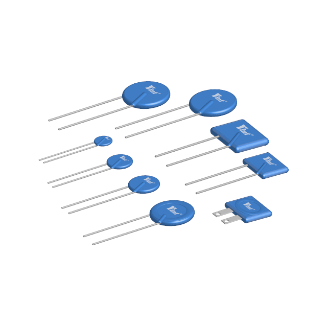
3.1 Voltage sampling and acquisition circuits
For smart meters, voltage signal collection is required, while the voltage and sampling methods of single-phase and three-phase meters are different. The following figure shows the voltage acquisition input terminal of a single-phase meter.

Figure 6 Single-phase smart meter voltage acquisition input
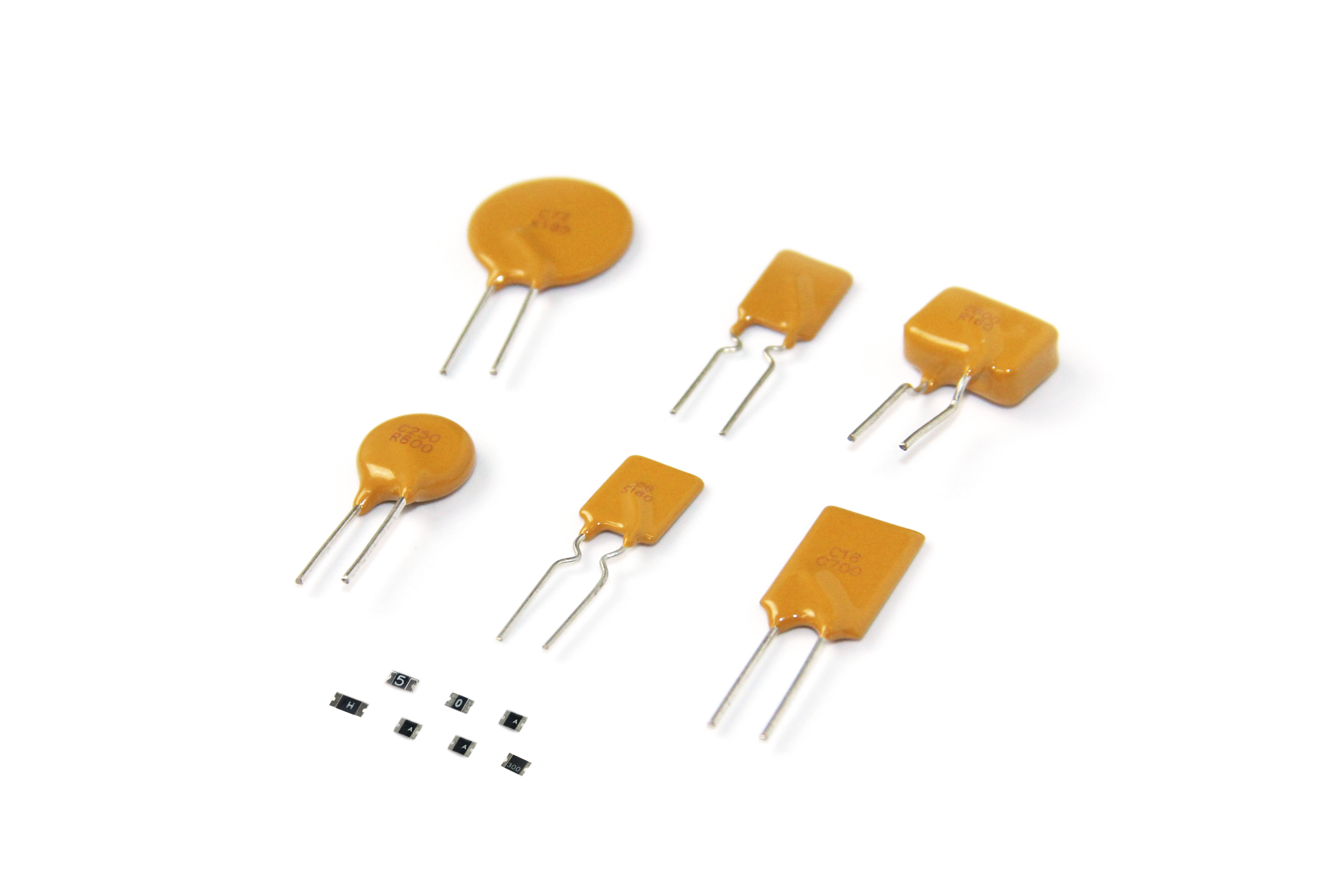
YINT recommends using varistors for input overvoltage protection. The recommended models are 14D or 20D products with voltages of 470V (single-phase 220V) ~ 820V (three-phase 380V):

Table 1 Selected parameters of the 14D and 20D varistors from YINT
3.2 Current sampling acquisition circuit
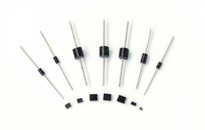
At the current collection input end of smart meters, TVS is often used for surge protection to protect subsequent metering chips.

Figure 7 Smart meter current collection input interface circuit
YINT recommends TVS model as SMBJ6.5CA or P6SMB6.8CA. Some of its parameters are as follows:

Table 2 Selected parameters of the YINT SMBJ6.5CA and P6SMBJ6.8CA
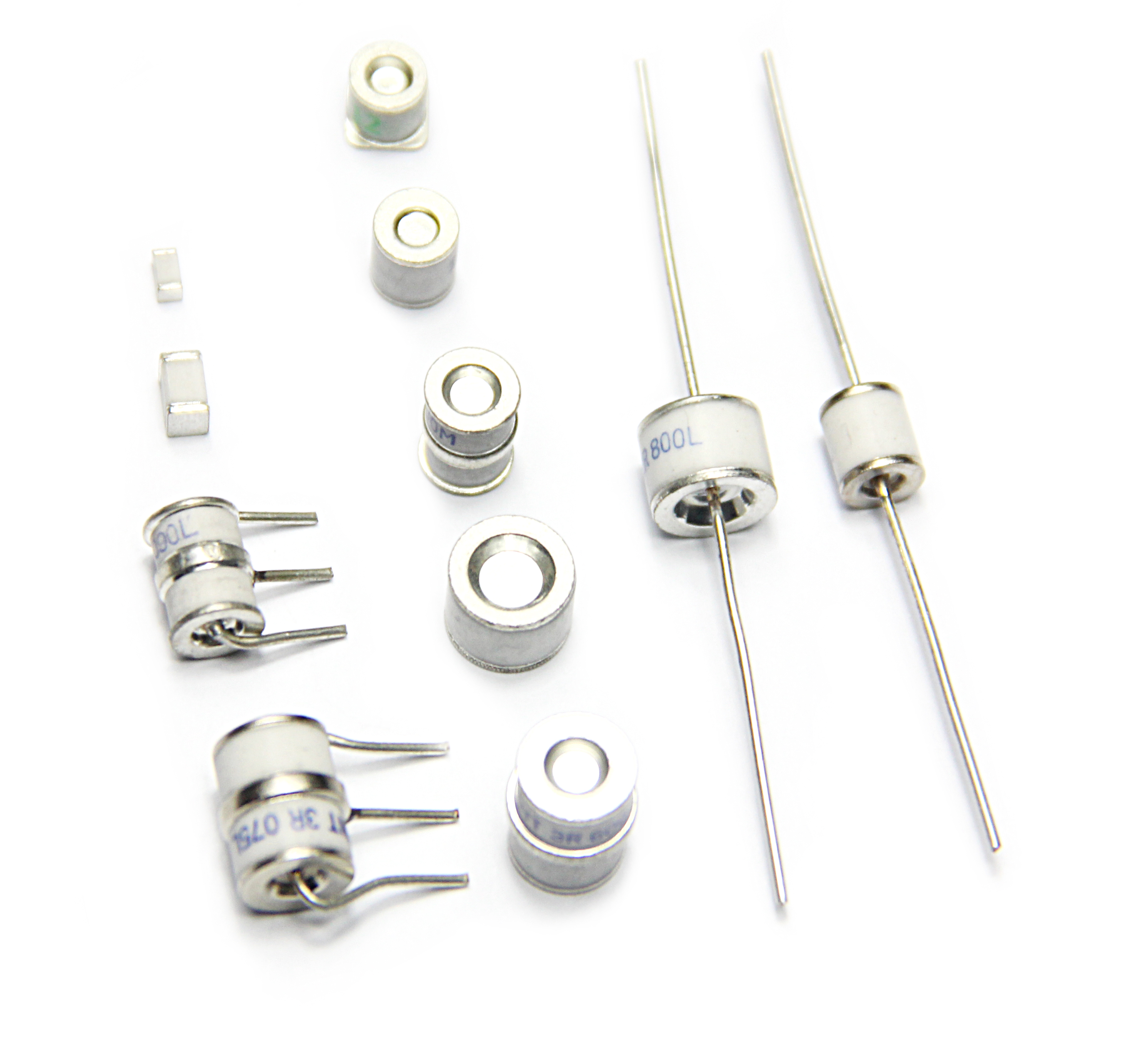
3.3 PLC interface circuit of power line carrier communication
Power Line Carrier PLC (Power Line Communication) has many application scenarios. The carrier circuit loads the communication signal to the power line through FSK and other methods, and receives the signal transmitted from other systems through the power line and demodulates the relevant data.
The following figure shows a power carrier interface circuit.

Figure 8 Power carrier interface circuit

Table 3 Recommended devices for phonetic protection of power carrier interface circuits
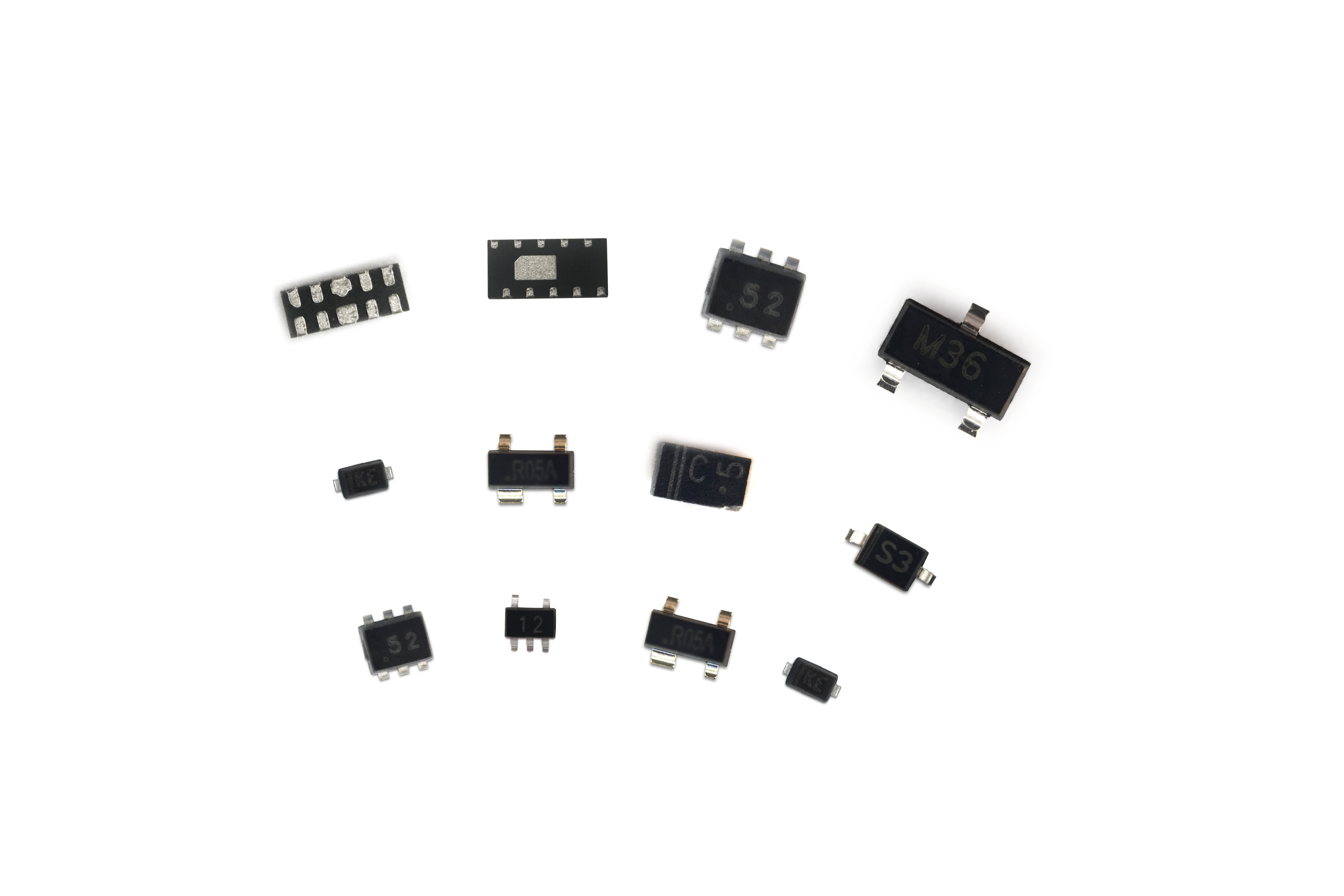
3.4 RS485 communication interface circuit
RS485 communication is often used between the collector and the smart meter, or between the collector and the concentrator. Due to the complex and uncontrollable electromagnetic environment, RS485 chips are often impacted by surges and electrostatic shocks, causing damage to the system or components.

Figure. 9 Schematic diagram of the RS485 communication interface protection circuit
YINT recommends RS485 communication port, using ESDSM712 electrostatic protection device. ESDSM712 adopts 7V, 12V asymmetrical internal structure, which can suppress the static electricity or surge of common mode 12V and differential mode 14V for RS485 dual-line. The main parameters are:


Table 4 Selected parameters of ESDSM712 protection devices
3.5 Chip power supply protection
For the key chips in the system, the power supply input terminal of the TVS can use the ps-level response speed and precise clamping characteristics of the TVS to protect the power supply terminal of the chip from surge.

Figure 10 Schematic diagram of the main chip power protection circuit
YINT recommends the surge protection device for the main MCU power supply side: SMF5.0CA

Table 5 Selected characteristic parameters of SMF5.0CA
3.6 Wireless communication antenna protection
For the wireless communication module of the collector or concentrator, it is often necessary to perform electrostatic protection on the antenna interface end to prevent electrostatic disturbance from the antenna end, which affects the normal operation of the wireless communication module.

Figure 11 Schematic diagram of the antenna transceiver module protection circuit
YINT recommends the use of low-capacity small package electrostatic protection device ESDLC5V0D9B, the package is SOD923, the capacitance is as low as 0.5pF, and the static electricity can reach up to ±30kV.
4. summary
With the development of the Internet of Things, more and more IoT meters have been developed for remote centralised meter reading systems, and there have been many changes in communication modes. YINT has also been tracking technological trends and devoting human and material resources to research protection solutions under new application scenarios to provide design references for all technical engineers.
5. References
(slightly)
Welcome to inquire, discuss and apply for samples