1. In an automotive engine's EMS system, how much impact does electromagnetic interference (EMI) generated by spark plug ignition have on EMS sensor signals? How can it be mitigated?
Answer: Impact: The instantaneous spark plug ignition generates tens of thousands of volts of high voltage, which penetrates the air and generates a strong electromagnetic pulse (EMP). This is a broadband interference (ranging from megahertz to gigahertz). This interference can affect EMS sensor signals through both radiation (patial coupling) and conduction (through power lines and grounding wires). This is particularly true for low-frequency (mV-level) signals such as those from crankshaft position sensors, camshaft sensors, and oxygen sensors. This can cause signal distortion and false triggering, leading to unstable engine idle, knock control failure, or even stalling.
Protective Measures
Shielding Design: Sensor cables utilize double shielding (inner insulation shield + outer grounding shield). The shields must be reliably grounded at one or both ends (depending on the frequency, grounding at both ends is recommended for high frequencies). Spark plug high-voltage wires utilize shielded wire with a magnetic core, with the shields grounded to the engine block at multiple points.
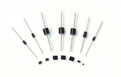
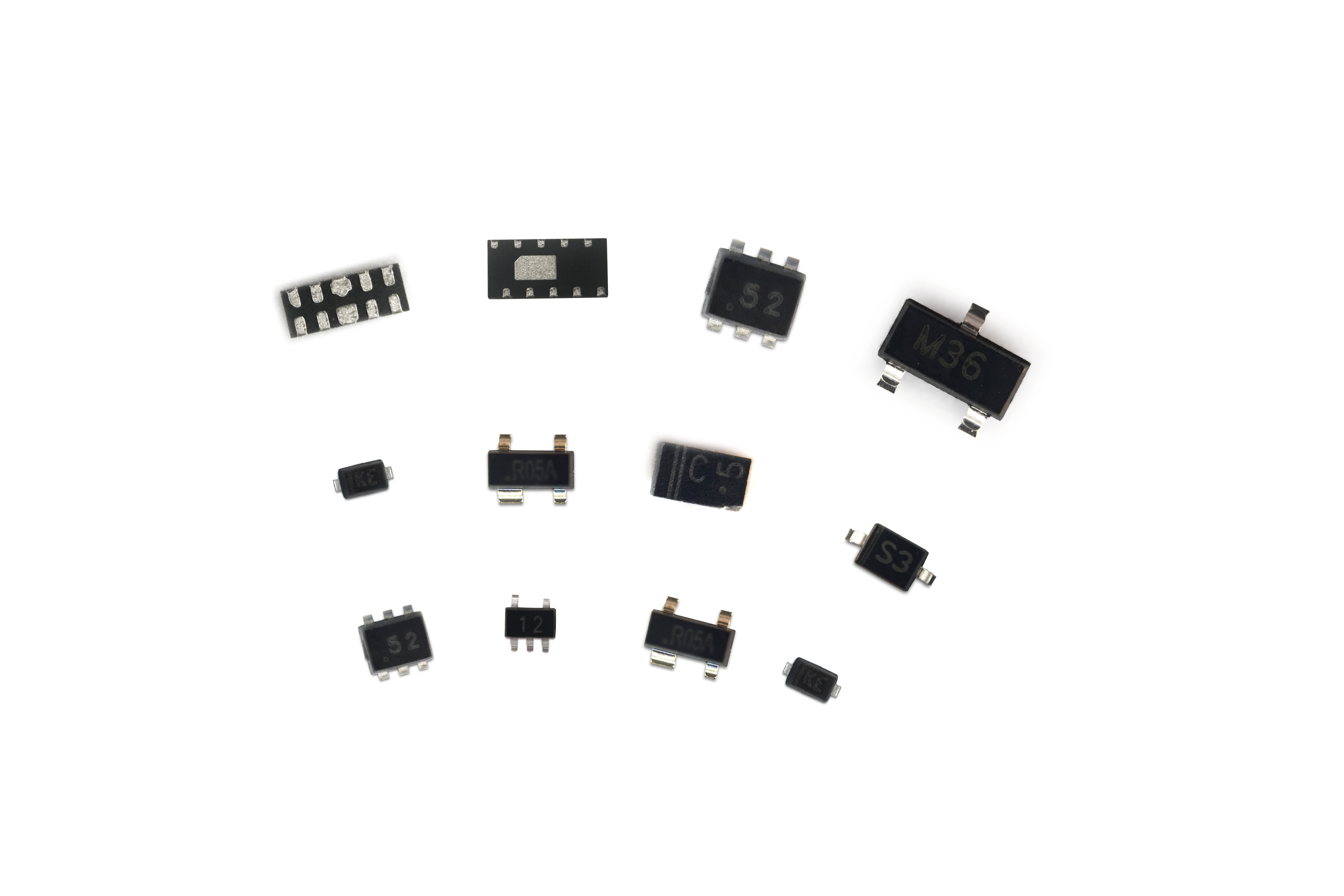
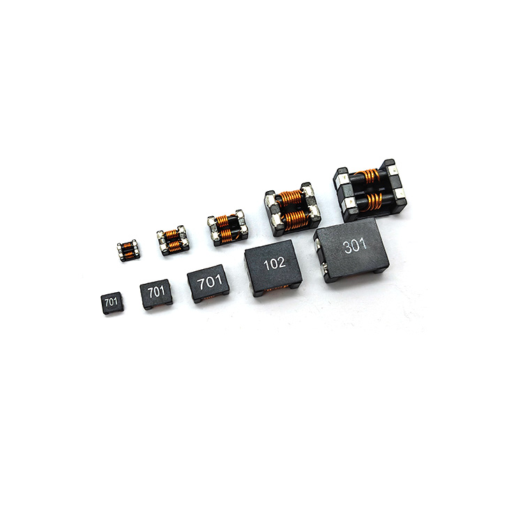
Filtering: Connect an RC filter or common-mode inductor in series with the sensor signal input to suppress high-frequency interference. Install a TVS diode and π-type filter on the power line to absorb transient pulses.
Optimized Wiring: Route sensor cables away from interference sources such as spark plug high-voltage wires and ignition coils, avoiding parallel routing. Signal and power lines must be separated, with a spacing of ≥30cm.
2. What impact does the bumps and vibrations of a vehicle during driving have on the electromagnetic compatibility of the EMS? How can these factors be considered in the design to ensure reliable EMS operation?
Answer: Impact: Bumps and vibrations may cause the EMS's mechanical structure to loosen, leading to the following EMC issues.
Poor connector contact: Oxidation or loosening of pins can cause impedance fluctuations, increasing the coupling path for electromagnetic radiation and conducted interference.
Shield failure: Loosening of the connection between the cable shield and the ground terminal reduces shielding effectiveness and makes it ineffective in blocking external interference or internal radiation.
Component parameter drift: Micro-displacement of surface-mount components, inductor cores, etc. due to vibration can cause changes in capacitance and inductance, degrading filter performance.
Design solutions:
Mechanical reinforcement: Use automotive-grade connectors with locking latches (such as the AMP MCP series). Use gold-plated pins to prevent oxidation. Use ribs to secure the PCB. Apply adhesive (thermal adhesive + (Structural adhesive) reinforcement
Shielding reliability: The shield layer and ground terminal are crimped or welded (avoid screw connections). The cable fixing clips are spaced ≤ 30cm apart to prevent friction and wear of the shield layer during vibration.
design: Critical signals (such as crankshaft position signals) are transmitted using two-wire differential transmission. When vibration causes single-channel interference, differential amplification can be used to suppress common-mode interference.
3. How is electromagnetic compatibility coordinated between automotive electronic EMS and other in-vehicle electronic systems (such as entertainment systems and navigation systems)? What are the potential sources of interference and interference?
Answer: Potential Interference Sources and Victims
Interference Sources: Entertainment system (radio, Bluetooth module, operating at 88-108MHz, 2.4GHz), navigation system (GPS 1.5GHz), air conditioning compressor (motor commutation interference, 100kHz-10MHz), on-board charger (switching power supply noise, 50kHz-1GHz)
Victims: EMS sensors (low-frequency, small signals), CAN bus (differential signals, susceptible to common-mode interference), MCU (clock frequency 10-100MHz, susceptible to RF interference)
Coordination Measures
Frequency Planning: Avoid overlap between EMS key signal frequencies (such as sensor sampling frequency, CAN bus baud rate 500kbps/1Mbps) and the entertainment system RF frequency; adjust the MCU clock frequency through software to avoid interfering frequency bands.
Physical Isolation: Maintain a distance of 50cm or greater between the EMS control unit and the entertainment system and navigation modules, avoiding co-housing installation. Route cables separately (power cables and signal cables in separate bundles), with 90-degree angles when crossing. Vertical crossover reduces coupling.
Ground partitioning: The EMS ground system (signal ground, power ground) is separated from the entertainment system ground. Grounding is achieved through a single point of convergence on the vehicle shell to avoid ground loop interference.
4. How do different automotive operating environments (such as high temperature, low temperature, and humidity) affect the electromagnetic compatibility of the EMS? How should the EMS be designed to adapt to these varying environments?
Answer: Impacts of Different Environments
High Temperature (-40°C to 125°C): Capacitors (especially electrolytic capacitors) experience reduced capacitance and increased ESR, shifting the filter cutoff frequency. Magnetic core materials (such as ferrites) experience decreased magnetic permeability, weakening common-mode inductance suppression capabilities and potentially exceeding radiated emissions standards.
Low Temperature: Plastic casing shrinkage leads to poor shield contact. Cable insulation hardens, causing friction between shield and insulation to generate static interference, impacting low-level sensor signals.
Humidity: Condensation on the PCB surface increases leakage current, ground impedance, and common-mode interference coupling. Oxidation on connector pins increases contact resistance and enhances conducted interference coupling paths.
Design Adaptability
Component Selection: Use automotive-grade, wide-temperature components (such as ceramic capacitors instead of electrolytic capacitors, with a temperature resistance of -55°C to 150°C). Use nickel-zinc ferrite for cores (which offers superior high-temperature stability over manganese-zinc).
Protective Technology: PCBs are coated with conformal coating (≥50μm thick) to protect against moisture and corrosion. Connectors are IP6K9K rated, with nickel-plated pins. Gold plating
Thermal management: Install a heat sink on the EMS control unit to ensure the internal temperature is ≤85°C (temperature of key components); optimize the layout through simulation to avoid close thermal coupling between power devices (such as MOSFETs) and sensitive circuits (such as ADCs).
5. In automotive electronics EMS, what failure symptoms will occur when CAN bus communication is subject to electromagnetic interference? How can the CAN bus's anti-interference capabilities be improved through both hardware and software?
Answer: Symptoms: Increased communication error frames, bus utilization exceeding 10% (normal ≤5%)
Data loss or bit errors, such as sudden changes in parameters like engine speed and water temperature
In severe cases, the bus "locks," disrupting communication between the EMS and other nodes (such as the ABS and TCU), causing the vehicle to enter limp mode
Anti-interference measures
Use shielded twisted-pair CAN bus cables, with the shield grounded at one end (near the EMS end) and impedance matching (120Ω termination resistors)
Install common-mode inductors (such as TDK's ACM series) at both ends of the bus to suppress common-mode interference; connect TVS diodes (such as SMBJ6.5A) in parallel at node interfaces to absorb transient pulses
Implement CRC checksums and frame retransmission mechanisms (up to 3 times) to detect and correct bit errors
Design a "bus watchdog" to detect errors when error frames persist for more than 100ms When a fault occurs, the node is automatically reset and reconnected to the bus.
Critical data (such as injection commands) is transmitted using redundant frames to improve reliability.
6. How do changes in the vehicle's electrical load (such as turning headlights on and off) affect the electromagnetic compatibility of the EMS? How should the EMS respond to such changes?
Answer: Impact: The switching of loads such as headlights, air conditioning compressors, and wipers can cause transient voltage fluctuations in the power bus (12V/24V) (e.g., a 1-2V drop when the headlights are on, and a 5-10V spike when they are off). This is considered conducted interference (10kHz-1MHz). This interference can couple to the internal circuitry through the EMS power input, causing the MCU to reset and unstable sensor power supply (e.g., fluctuations in the 5V reference source), impacting signal acquisition accuracy.
Countermeasures
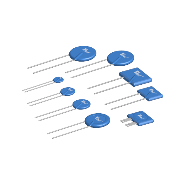
• Power supply filtering: Design multi-stage filtering at the EMS power input: a first-stage TVS diode (e.g., 1.5KE15A) absorbs high-voltage spikes; a second-stage π-type filter (inductor + capacitor, e.g., 100μH inductor + 10μF electrolytic capacitor + 0.1μF ceramic capacitor) suppresses low-frequency fluctuations; a third-stage LDO (low-dropout regulator, e.g., TI's TPS7A4700) provides a stable 5V/3.3V supply with ripple ≤1mV.
• Load isolation: Route the power lines for high-power loads (e.g., headlights) separately from the EMS power lines to avoid parallel connections; connect an RC snubber circuit (e.g., 100Ω resistor + 100nF capacitor) in parallel with the load switch to reduce switching transients.
• Software compensation: Use the ADC to compensate for transients. Monitor the power supply voltage in real time. If fluctuations exceed ±5%, suspend non-critical tasks (such as diagnostics) and prioritize core controls like fuel injection and ignition. Restart tasks after voltage returns to normal.
7. What types of electromagnetic interference (EMI) does the electric power steering (EPS) system in automotive electronics (EMS) generate? How does this interference affect other parts of the EMS? How can it be mitigated?
Answer: Interference Type: The electric power steering (EPS) motor (DC or permanent magnet synchronous motor) generates conducted interference (through the power line) and radiated interference (through the motor cable) during commutation. The main frequency ranges are:
Impact on the EMS: Interference can couple to EMS sensors (such as the throttle position sensor) through the power supply, causing signal drift; it can couple to the CAN bus through spatial radiation, causing communication errors; in severe cases, it can interfere with the MCU's clock circuit, causing program errors.
Mitigation Measures:
Motor-End Filtering: Connect a common-mode inductor (such as the Epcos B82731 series) in series with the EPS motor output, along with an X2 safety capacitor (0.1μF) and a Y capacitor (10nF) in parallel to suppress conducted interference. Ensure the motor housing and vehicle body are reliably grounded (impedance ≤ 1Ω).
Cable Shielding: Use shielded twisted-pair cables for the EPS motor. Ground the shield at both ends (motor and EPS controller) and to the EMS. Keep cables ≥30cm apart and avoid parallel routing.
Isolation design: Physically isolate the EPS controller from the EMS power and ground systems (via optocouplers or isolated power supplies, such as TI's ISO7740) to block common-mode interference paths.
8. In hybrid or electric vehicles, what are the special electromagnetic compatibility requirements of the high-voltage battery system for the EMS? How should the EMS meet these requirements?
Answer: Special requirements: The inverter (which converts DC power to three-phase AC to drive the motor) of the high-voltage battery system (200-800V) generates strong common-mode interference (primarily from IGBT switches) with frequencies up to 100MHz. Furthermore, parasitic capacitance coupling exists between the high-voltage circuit and the low-voltage EMS (12V), which may cause...
Common-mode currents may form loops through the vehicle body ground, interfering with the EMS sensors and communication bus.
High-voltage arcs (e.g., connector plugging and unplugging) generate electromagnetic radiation, affecting the EMS's noise immunity.
Methods to meet these requirements:
Reinforced isolation: Reinforced insulation (withstand voltage ≥ 2kV) is used between the EMS and the high-voltage system. Critical signals (such as the high-voltage interlock signal) are transmitted via digital isolators (such as Silicon Labs' Si86xx) with an isolation voltage ≥ 5kV.
Common-mode filtering: Common-mode inductors (with nanocrystalline alloy cores for low high-frequency loss) and Y capacitors (≤ 100nF, meeting safety standards) are installed at the output of the high-voltage inverter to suppress common-mode currents. The EMS's 12V Install a multi-stage common-mode filter (cutoff frequency ≥ 100MHz) at the power input.
Grounding optimization: The high-voltage system should be grounded separately (insulated from the vehicle body), and the EMS ground should be connected to the vehicle body at a single point to prevent high-voltage common-mode current from flowing into the EMS ground loop. High-voltage cables should be fully shielded, with the shield grounding impedance ≤ 0.5Ω.
9. What impact might electromagnetic radiation from automotive EMS have on external electronic equipment (such as traffic signal systems and other nearby vehicle electronic equipment)? How can this impact be controlled?
Answer: Potential Impact: EMS radiated interference (primarily from the MCU clock, switching power supply, and sensor cables) may affect:
Traffic signal systems: Interference with RF communication modules (e.g., 2.4GHz wireless transmission), leading to signal misjudgment.
Nearby vehicles: Interference with radar sensors (e.g., 77GHz millimeter-wave radar) through radiation coupling, causing false alarms or ranging errors.
Civil communications: Such as AM/FM radio (88-108MHz) and 4G/5G base stations (700MHz-6GHz), resulting in increased noise in received signals.
Control Methods:
Radiation Suppression: Optimize the EMS PCB layout, routing clock lines and high-speed signal lines (e.g., SPI) on inner layers with matching resistors at both ends. Place the switching power supply's inductor and capacitor close to the chip to reduce loop area (≤1cm²) and lower radiation source intensity.
Improved Shielding Effectiveness: The EMS control unit housing is made of aluminum alloy (thickness ≥1mm), with seams sealed with conductive adhesive, achieving a shielding effectiveness of ≥60dB (100MHz-1GHz). Internal sensitive circuits (e.g., ADC) isolated with a metal shield.
Compliance with standards: Meet the radiated emission limits in CISPR 25 (Automotive Electronics EMC) (e.g., 30MHz-1GHz, Class 5 equipment limit ≤40dBμV/m@3m). Optimize the design through spectrum analyzer pre-testing.
10. During automotive EMC testing, which test items do EMS typically encounter problems? What are common solutions to these problems?
Answer: Common Problems and Solutions
1. Radiated Emissions Exceed Standards (30MHz-1GHz)
Problem: MCU clock line and CAN bus are unshielded, or the filter cutoff frequency is insufficient.
Solution: Add a 50Ω resistor in series with the clock line to suppress reflections and ground the outer shielding tube. Add a common-mode inductor (e.g., 1000nH) to the CAN bus and adjust the filter capacitor value (increase the filter capacitor by 0.1μF).
2. Sensor Failure During Immunity Testing (ISO 11452-2)
Problem: The sensor signal is not filtered and is sensitive to radiated interference (e.g., 200V/m electric field).
Solution: Add an RC filter (1kΩ + 10nF) in series with the sensor signal line. Use a double-shielded cable with both ends of the shield grounded.
3. Conducted Emissions Exceed Standards (150kHz-30MHz)
Problem: The power supply filter does not adequately suppress low-frequency interference (e.g., 100kHz noise from the switching power supply).
Solution: Increase the filter inductance (from 100μH to 100μH). 330μH), parallel X2 capacitors (0.22μF), and optimized grounding layout (connect the filter housing and EMS housing at multiple points).
4. MCU reset in transient immunity (ISO 7637-2)
Problem: The power supply terminal does not effectively absorb pulses (e.g., 50V/50Ω pulses).
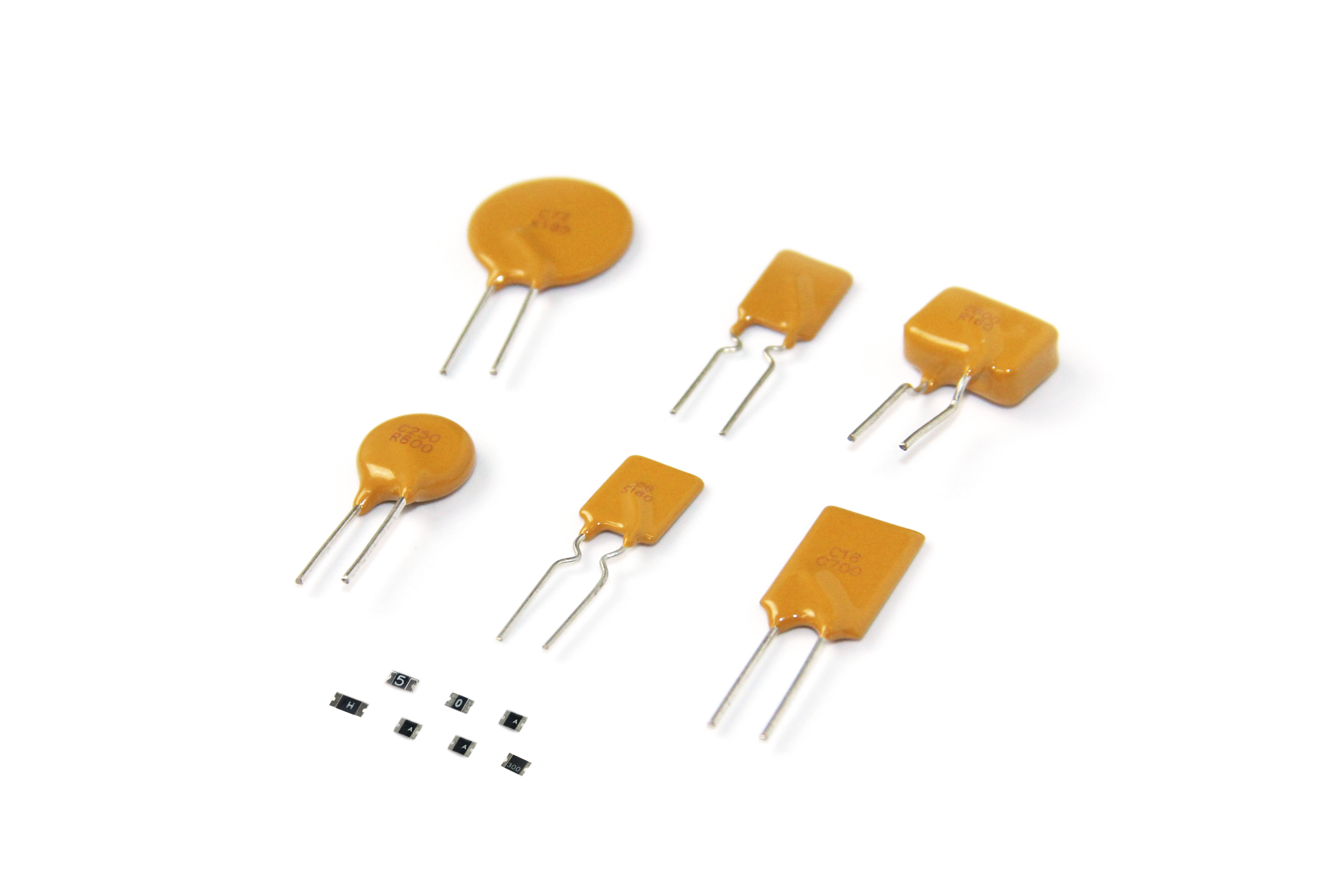
Solution: Connect a PTC fuse (current limiting) in series with the power inlet, and connect a TVS diode (1.5KE18A) and a storage capacitor (100μF) in parallel to absorb transient energy.
11. What types of electromagnetic interference are electronic throttle control (ETC) systems in automotive EMS susceptible to? How can their anti-interference capabilities be enhanced?
Answer: The electronic throttle control (ETC) system consists of a throttle position sensor, a drive motor, a control chip, and wiring harness. It is susceptible to the following electromagnetic interference:
Conducted interference: Voltage fluctuations from the vehicle's power supply (such as transient low voltage during startup and switching spikes from high-power devices), and noise coupled through the power lines from other controllers (such as ESP).
Radiated interference: High-frequency radiation (10MHz-1GHz) from spark plug ignition, switching noise (MHz-level) from the motor drive circuit, and radio frequency signals from wireless communication modules (such as Bluetooth and 4G).
Electrostatic discharge (ESD): Static electricity from human contact with the throttle interface during maintenance or use may enter the control chip through the wiring harness.
Measures to enhance interference resistance:
Hardware design: Connect a TVS diode and a π-type filter (LC combination) in series at the ETC power input to suppress conducted interference on the power line. The throttle position sensor uses differential signal transmission (such as the SENT protocol) to reduce common-mode interference. An RC snubber network (to suppress switching spikes) and a ferrite bead (to absorb high-frequency noise) are connected in parallel to the motor drive circuit.
Shielding and wiring: ETC The controller housing is grounded. The sensor and motor wiring harnesses use twisted-pair cables with aluminum foil shielding, with the shield grounded at one end (near the controller). Keep the wiring harness away from strong interference sources such as spark plug high-voltage wires and motor drive lines.
Software Optimization: Add signal filtering algorithms (such as sliding average filtering) to the control chip to perform redundancy checks on sensor signals. Implement a fault self-diagnosis function to trigger a safety mode (such as limiting throttle opening) when abnormal signals are detected.
12. How does the electromagnetic compatibility of the EMS change under different vehicle driving conditions (such as acceleration, deceleration, and constant speed)? How can this be optimized?
Answer: The differences in EMS electromagnetic compatibility (EMC) performance under different driving conditions are primarily due to the switching frequency, current change rate (di/dt), and load fluctuations of power devices.
Acceleration: Engine speed increases rapidly, increasing the fuel injection and ignition frequencies. The injectors and ignition coils switch more frequently, increasing di/dt and leading to increased radiated interference (especially in the 10-100MHz frequency band). Furthermore, the EMS samples sensor signals (such as crankshaft position and intake pressure) at a higher frequency, increasing the likelihood of interference.
Deceleration: When coasting with the fuel cut off, some vehicles deactivate the injectors, but the reduced throttle opening may cause turbulence in the intake system, affecting the stability of the intake pressure sensor signal. In hybrid/electric vehicles, reverse motor power generation may generate reverse voltage spikes, which may interfere with the EMS through power coupling.
Constant speed operation: The system load is stable, the power device switching frequency is fixed, and electromagnetic interference is relatively mild. However, long-term operation may cause poor contact due to wiring harness vibration, introducing intermittent interference.
Optimization measures
Dynamic adjustment of control parameters: During acceleration, reduce the rise/fall time of the PWM drive signal (by optimizing the gate resistor) to reduce di/dt; during deceleration, increase the capacitance of the power filter (for example, by connecting a 10μF electrolytic capacitor and a 0.1μF ceramic capacitor in parallel to the EMS power supply) to suppress voltage fluctuations.
Adaptive filtering: Software-level filtering algorithms are switched based on operating conditions (for example, using a fast Fourier transform (FFT) to filter out noise in specific frequency bands during acceleration, and using a simple RC filter during constant speed).
Mechanical reliability design: Use vibration-resistant connectors (such as AMP Tyco's snap-on connectors) for the wiring harness, and add shock-absorbing pads to the sensor mounting bracket to prevent vibration-induced changes in contact impedance.
13. How is electromagnetic compatibility between the in-vehicle network system (such as LIN, FlexRay, etc.) and the EMS in automotive electronics ensured? What are the key technical points?
Answer: EMC protection for in-vehicle networks (LIN, FlexRay, CAN, etc.) and EMS requires addressing interference coupling during signal transmission and electromagnetic radiation from network nodes. Key technical considerations are as follows:
1. Physical Layer Design
LIN bus: Single-ended signal transmission (0-12V) is susceptible to common-mode interference. A 1kΩ termination resistor and a 10-100μH common-mode inductor are required at the node end to suppress common-mode noise. Twisted-pair cables (20-30mm twist length) are used to minimize radiation.
FlexRay bus: High-speed (up to 10Mbps) differential signal transmission requires strict control of differential impedance (100Ω ± 20%). Impedance matching (100Ω termination resistor) is used to minimize signal reflections. Shielded twisted-pair cables are used, with the shield grounded at both ends to prevent ground potential differences.
2. Grounding and Isolation
When network nodes and EMS controllers share a common ground, a single-point connection using a 0Ω resistor or ferrite bead is required to prevent ground loops. If the node is grounded, the ground must be grounded at the same point. EMS power supply isolation (e.g., using a DC-DC isolation module for LIN slave nodes) requires the use of an isolated transceiver (e.g., TI's ISO1050) to block common-mode interference paths.
3. Protocol-layer interference mitigation
Error handling: The LIN protocol supports checksums, while FlexRay supports cyclic redundancy checks (CRCs) and frame retransmission mechanisms, which can identify and discard erroneous frames.
Rate adaptation: Non-critical data (e.g., throttle position feedback transmitted via LIN) can have its transmission rate reduced (e.g., from 19.2kbps to 9.6kbps) to reduce high-frequency radiation.
4. Layout and wiring
Network wiring harnesses should be routed away from EMS power circuits (e.g., ignition coil drivers and injector drivers) and high-voltage wiring harnesses (e.g., high-voltage cables for hybrid vehicles), maintaining a minimum spacing of 30cm. If crossing, they should cross perpendicularly (to reduce coupling area).
14. How does a vehicle's metal body affect the electromagnetic compatibility of the EMS? How can the vehicle body structure be used to improve the electromagnetic compatibility of the EMS?
Answer: A car's metal body (mostly steel or aluminum alloy) has a dual impact on the EMS's EMC. Proper utilization can significantly improve the system's interference resistance.
Positive Impact: As a continuous conductor, the body acts as an electromagnetic shield, preventing external radiated interference (such as radar and radio signals) from intruding into the EMS. Furthermore, the body provides a good ground reference point, reducing the system's ground impedance.
Negative Impact: Gaps and holes in the body (such as wiring harness holes between the engine compartment and the cockpit) can become radiation leakage channels, allowing interference within the EMS (such as ignition noise) to escape. Ground potential differences between different parts of the body (due to high current flow) can form ground loops, leading to common-mode interference.
Methods for Improving EMC Using Body Structure
1. Shielding Enhancement
The EMS controller (such as the ECU) in the engine compartment is mounted directly on a metal bracket in the body. Conductive padding (such as conductive foam) ensures a tight connection between the controller housing and the body, forming a "Faraday cage" to shield internal radiation and external
Install metal shielding rings (such as EMI shielding glands) at wiring harness holes to seal the holes and prevent interference from propagating through the gaps.
2. Grounding Optimization
3. Suppressing Eddy Currents and Radiation
Apply conductive adhesive to vehicle body joints (such as those between the door and the vehicle body) to reduce contact impedance and prevent eddy current radiation generated by high-frequency currents in the gaps.
Ground wires for high-power devices (such as generators and motors) should be connected to the vehicle body as close as possible to shorten the high-frequency current path and reduce radiation from the vehicle body acting as an antenna.
15. What failures may occur when an automotive electronic EMS is struck by lightning or electrostatic discharge? How can the EMS be designed to improve its lightning protection and electrostatic discharge resistance?
Answer: The impact of lightning or electrostatic discharge (ESD) on the EMS and the protective measures are as follows.
Possible Failures
Power chip (such as LDO, DC-DC) breakdown
Sensor signal distortion (such as abnormal crankshaft position sensor output, resulting in ignition timing errors)
Communication bus (CAN, LIN) failure, resulting in loss of connection between the EMS and other controllers
Gate oxide breakdown in the control chip (MCU, DSP)
Transient interference can trigger a software reset, causing the EMS to enter fault mode (such as engine stall).
Protection Design
1. Lightning Protection Measures
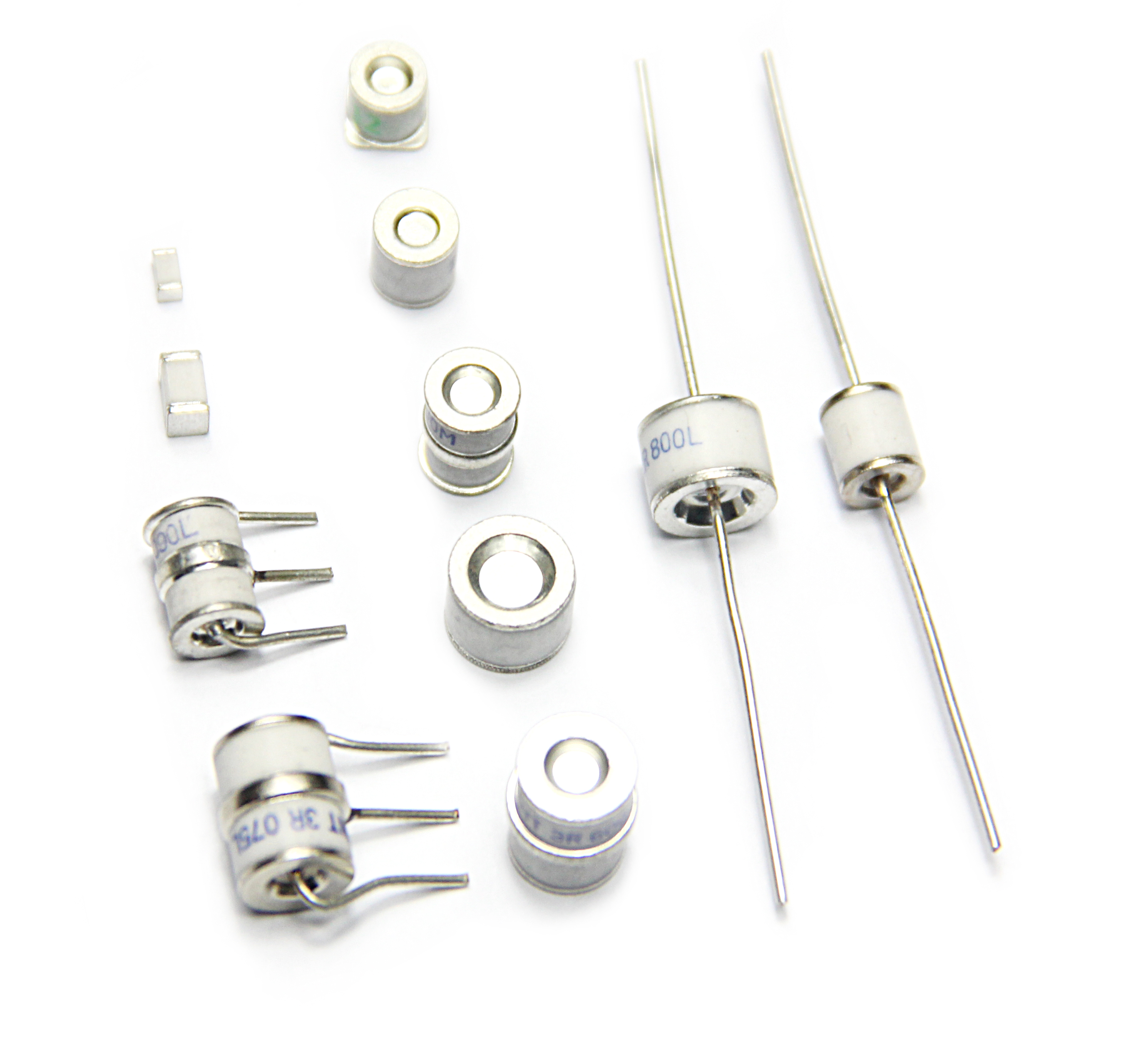
Power Supply Protection: Connect a gas discharge tube (GDT, e.g., 230V breakdown voltage) and a TVS in series at the EMS power input. Diodes (e.g., 600W peak power) are used to dissipate high currents generated by lightning strikes; common-mode inductors (100-500μH) are added to power lines to suppress common-mode transient noise.
Signal Protection: Transient suppressor diodes (TVS diodes, e.g., with a breakdown voltage of 33V) and ferrite beads are connected in series with sensor signal lines (e.g., oxygen sensors and knock sensors) to reduce coupled transient voltages.
2. ESD Protection Measures
Interface Protection: TVS diodes (±15kV ESD protection) are connected in parallel between the pins of the diagnostic interface (OBD-II) and the housing. The housing is directly connected to the vehicle body ground. Sensor plugs use ESD-protected connectors (e.g., TE Connectivity's ESD-protected connectors).
Circuit Design: Current-limiting resistors (100-1kΩ) are connected in series with MCU I/O ports, along with small capacitors (10-100pF) in parallel to mitigate ESD. The injected current rise rate; analog circuits (such as preamplifiers) use differential inputs to improve the common-mode rejection ratio (CMRR>80dB).
Software fault tolerance: Set a watchdog timer to automatically reset if ESD causes program failure; increase redundant sampling of key sensor signals (such as a dual-channel crankshaft position sensor) to switch to the backup channel in the event of an abnormality.
16. Does the fuel injection system in the automotive electronic management system generate electromagnetic interference during operation? If so, how can it be suppressed to avoid impacting other systems?
Answer: The fuel injection system (consisting of injectors, driver circuits, and fuel pumps) is one of the main sources of electromagnetic interference in the EMS. The interference generation mechanism and mitigation measures are as follows:
Generation of Electromagnetic Interference
Injector Switching Noise: The injector is an inductive load (coil inductance is approximately 10-30mH). When the driver circuit is turned off, the coil's magnetic field energy releases, generating a voltage spike (up to 100-300V). This voltage spike is radiated through the power lines and into space (primarily in the 1-100MHz frequency band), causing interference.
Fuel Pump Motor Interference: When the DC motor of the electric fuel pump commutates, friction between the brushes and the commutator generates sparks, releasing broadband radiation (1MHz-1GHz). This radiation is also conducted through the power lines to the EMS and other systems (such as the radio).
Mitigation Measures
1. Injector Driver Circuit Optimization
A parallel RC snubber network (resistance 100-500Ω, capacitance 0.1-1μF) can be used to absorb the turn-off spike; or a freewheeling diode (such as a fast recovery diode) can be used. FR107) provides a discharge path for coil current and reduces spike voltage.
Select a soft-switching driver chip (such as Infineon's TLE8209). By controlling the MOSFET's turn-off speed (increasing gate resistance), di/dt is reduced, thereby lowering radiation.
2. Wiring and Shielding
Use shielded twisted-pair cables for the injector wiring harness. Ground the shield at one end (near the EMS controller) to minimize radiation. Keep the wiring harness away from sensitive devices such as the radio antenna and navigation module, with a spacing of ≥ 20 cm.
Integrate an EMI filter (such as a common-mode inductor + X-capacitor combination) in series with the fuel pump power line to suppress conducted interference. Ground the pump's metal casing to act as a radiation shield.
3. System-Level Isolation
17. How can the reliability of sensors (such as oxygen sensors and wheel speed sensors) in automotive EMS systems be guaranteed in electromagnetic interference environments? What protective measures are in place?
Answer: Sensors in the EMS (mostly with weak signal outputs, such as oxygen sensors outputting 0.1-0.9V and wheel speed sensors outputting mV AC signals) are extremely susceptible to electromagnetic interference, leading to signal distortion or misinterpretation. Protective measures must be implemented in three aspects: hardware, wiring, and algorithms.
Oxygen sensor (wideband or switching type)
Connect an RC low-pass filter (R = 1kΩ, C = 10nF, cutoff frequency ≈ 16kHz) in series with the signal line to filter out high-frequency noise.
Use single-ended shielded wiring. Connect the shield to the sensor housing and then to ground (to the vehicle body) to prevent noise coupling.
Use a sliding average filter (averaging 5-10 samples) in the software to smooth transient interference.
Wheel speed sensor (magnetoelectric or Hall effect)
Connect a TVS diode (breakdown voltage) in parallel with the output of the magnetoelectric sensor. 5V) to suppress electrostatic interference; twisted-pair signal cables (10-20mm twist pitch) are used to offset common-mode magnetic field interference.
The sensor and wheel hub connectors use waterproof and shockproof designs (e.g., connectors with O-rings) to prevent poor contact caused by vibration.
The software implements signal edge detection and verification (e.g., confirming wheel speed only after valid pulses are detected for three consecutive cycles to filter out single-pulse interference).
General Protection Principles
Power Supply Purification: A ferrite bead (100Ω @ 100MHz) and a small capacitor (0.1μF) are connected in series with the sensor power supply (e.g., 5V or 12V) to suppress power supply noise.
Isolation Design: A differential amplifier (e.g., INA128, CMRR > 100dB) is used between sensitive sensors (e.g., knock sensors) and the EMS control circuitry to improve common-mode interference rejection.
Redundancy: Critical sensors (e.g., crankshaft position sensors) use a dual-channel design, automatically switching to the other channel when interference occurs on one channel.
18. How can the diagnostic interface of an automotive electronic management system (EMS) prevent electromagnetic interference from affecting communication with external diagnostic equipment? What anti-interference measures are in place at the communication protocol level?
Answer: The EMS diagnostic interface (such as OBD-II) is a key node for communication between external devices (diagnostic instruments) and the EMS. It is susceptible to interference from the vehicle's electromagnetic environment (such as motor noise and wireless signals), requiring dual protection at both the hardware and protocol levels.
Hardware Protection Measures
Interface Circuit Protection: Connect a TVS diode (such as SMBJ33A, ESD protection ±15kV) and a common-mode inductor (10-100μH) in series with the CAN/LIN signal lines of the OBD-II interface to suppress transient interference. Connect a resettable fuse (such as 1A) and an LC filter in series with the power pin (pin 16) to prevent overcurrent and voltage spikes.
Shielding and Grounding: The diagnostic interface housing is directly connected to the vehicle body ground. The wiring harness uses shielded twisted-pair cables, with the shield layer conductively connected to the housing to reduce radiated interference coupling. A conductive gasket is added to the interface plug to ensure shield continuity during insertion and removal.
Isolation Design: Use an isolation chip (such as ADI's) between the diagnostic communication module (such as the CAN transceiver) within the EMS and the main control circuit. ADuM1400), blocking ground loop interference.
Protocol-Level Anti-Interference Measures
The CAN protocol uses a cyclic redundancy check (CRC) (15-bit CRC code) to detect errors during frame transmission and supports automatic retransmission (when an error is detected, the sending node resends the frame).
OBD-II is based on the SAE J1979 protocol, and data transmission adds a checksum (e.g., summing the PID and data bytes). The receiving end only interprets the data after verification.
Communication Rate Adaptation: In strong interference environments, the diagnostic device can negotiate a lower communication rate (e.g., CAN from 500kbps to 250kbps) to reduce bit errors caused by high-frequency noise.
Timeout and Fault Tolerance: If three consecutive communication failures occur, the EMS triggers communication interruption protection, records a fault code (e.g., P0607), and locally stores key parameters (e.g., speed, water temperature). Communication is restored after the interference is eliminated.
19. How does electromagnetic interference generated by the motor drive circuit in the automotive electronics EMS affect in-vehicle radio receivers (e.g., radios)? How can it be isolated or suppressed?
Answer: Motor drive circuits in the EMS (such as the cooling fan motor, fuel pump motor, and EPS motor) are sources of broadband electromagnetic interference. The impact of this interference on in-vehicle radio reception equipment (AM/FM radio, GPS) and the mitigation measures are as follows.
Interference Impact Mechanism
Radiated Interference: The high-frequency switching (10kHz-1MHz) of the MOSFET/IGBT in the motor drive generates rapid voltage/current changes (dv/dt, di/dt). This radiation forms an antenna through the motor wiring harness and drive circuit PCB, interfering with the radio's reception frequency band (AM: 530-1600kHz, FM: 87-108MHz). For example, a 1MHz switching frequency may fall into the FM band through harmonics (e.g., the 500th harmonic = 500MHz), causing radio noise and signal interruption.
Conducted Interference: Noise from the motor drive is conducted through the power line to the car radio's power module, coupling to its receiving circuitry (e.g., the tuner), affecting signal demodulation.
Isolation and Suppression Measures
1. Suppressing Radiated Interference
Motor Wiring Shielding: Use double-shielded twisted-pair cable (inner shield grounded at one end, outer shield grounded at both ends), with a shielding effectiveness of ≥60dB (10MHz-1GHz). Keep the wiring away from the radio antenna (at least 50cm away), and avoid parallel wiring.
Drive Circuit Shielding: Install the motor drive module (e.g., an IPM intelligent power module) in a metal shielded box. The box is grounded to the vehicle body to block the module's own radiation. In the PCB layout, separate the drive circuit and the control circuit (MCU), leaving a ground separation of ≥2cm between them.
2. Suppressing Conducted Interference
Power Supply Filtering: Connect an EMI filter (e.g., a π-type common-mode inductor + X capacitor + 100Ω) in series with the motor power line. Y capacitors), design cutoff frequencies for the AM/FM bands (e.g., AM band filter cutoff frequency < 500kHz, FM band < 100MHz); add a low-pass filter (RC or LC) to the radio power supply to filter out high-frequency noise.
Optimize switching frequency: Select the motor drive PWM frequency to avoid the radio's sensitive frequency band (e.g., avoid 1-10MHz and choose 15kHz or 20kHz) to reduce harmonics falling into the receive band.
3. Ground isolation: Connect the motor drive circuit ground and the radio ground at a single point using a 0Ω resistor to avoid ground loops. If interference is severe, use an isolated DC-DC converter (such as TI's DCP0105) to power the radio to achieve power isolation.
20. During the production and assembly of automotive electronic management systems (EMS), which steps may affect the EMS's electromagnetic compatibility? How is quality control conducted to ensure EMC compliance?
Answer: During the EMS production and assembly process, process defects can degrade EMC performance at multiple stages, requiring strict quality control to mitigate these issues.
Key Impacting Stages and Control Measures
1. PCB Soldering
Potential Issues: Weak solder joints (e.g., ground pads and shield pads) increase ground impedance, preventing effective noise dissipation; incorrect component soldering (e.g., incorrect ferrite beads or filter capacitance) lead to filter failure.
Control Measures: Use AOI (Automated Optical Inspection) to check pad wetting (solder coverage ≥ 90%); perform X-ray inspection on key components (e.g., common-mode chokes and TVS) to confirm the presence of voids within solder joints; sample 5% of PCBs from each batch for impedance testing (e.g., differential line impedance and ground resistance < 50mΩ).
2. Shield Termination
Potential Issues: Poor contact between the sensor/harness shield and the connector (e.g., loose crimping, oxidation), leading to reduced shielding effectiveness (e.g., from 60dB to 100dB). 30dB), unable to suppress radiated interference.
Control Measures: Use a dedicated crimping tool (such as JST's shield crimping die) to crimp the shield layer, ensuring the contact resistance between the shield layer and the connector housing is <10mΩ after crimping. 10% of each batch of harnesses undergo shield continuity testing (using a milliohmmeter to measure impedance at both ends).
3. Housing Assembly
Potential Issues: Poor ground connection between the EMS controller housing and the internal PCB (e.g., insufficiently compressed conductive gasket, loose screws), resulting in shield failure; excessive housing gaps (>0.5mm) create radiation leakage paths.
Control Measures: During housing assembly, control the compression of the conductive gasket (e.g., nickel-clad copper foam) to 30%-50%, and use a torque wrench to ensure the tightening screws are torqued to 2.5±0.2N·m. Use near-field scanning (100MHz-1GHz) to test the radiation intensity of the housing gap. Rework is required if the value exceeds the standard.
4. Harness Connection
o Potential Issues: The harness connector and the EMS Poor pin contact (e.g., bent or oxidized pins) on the interface introduces noise into signal transmission; bundling different types of wires (power and signal wires) too close together increases coupling interference.
Control measures: After plug assembly, perform insertion and removal force tests (e.g., ≥5N) and continuity tests (contact resistance <20mΩ). When bundling wires, maintain a spacing of ≥10cm between power wires (e.g., injector wires) and signal wires (e.g., sensor wires), and a spacing of ≤30cm between fixing clips to prevent positional shifting caused by vibration.
5. Factory Inspection
Each EMS unit must undergo EMC sampling testing (e.g., 10% of the total), including radiated emissions (CISPR 25 Class 3) and immunity (ISO 11452-2).
Incoming material inspection of key EMC components (e.g., filters and shielding covers) is performed (verification of specifications, impedance/shielding effectiveness testing) to eliminate counterfeit and substandard products.

