1. In the complex electromagnetic environment of a hospital, what external electromagnetic interference sources (such as other medical equipment and communications equipment) are medical equipment EMS susceptible to?
High-frequency electrosurgical units: During operation, they generate strong high-frequency (0.3-5 MHz) electromagnetic radiation, which
may interfere with nearby monitors and ultrasound equipment.
MRI/CT equipment: The strong magnetic field (1.5T/3.0T) and radio frequency pulses (64-300 MHz) of MRI equipment can interfere with magnetically sensitive circuits (such as inductors and magnetic sensors); the high-voltage generator of CT equipment may also generate pulse interference.
Defibrillators: The instantaneous discharge generates a strong current pulse, which can interfere with devices such as ECG monitors through conduction or radiation.
Ultrasound equipment: The high-frequency signal (2-20 MHz) of the probe driver circuit may cause radio frequency interference to nearby low-power devices.
Mobile phones and walkie-talkies: Radio frequency signals (800 MHz-5 GHz) may couple to sensitive circuits in medical equipment (such as bioelectrical detection circuits).
Wi-Fi base stations and Bluetooth devices: 2.4 GHz/5 GHz Wireless signals in the specified frequency band may interfere with the instrument's wireless module (such as Bluetooth communication).
Grid interference: Voltage fluctuations and harmonics (50Hz/60Hz and multiples thereof) caused by the start-up and shutdown of large hospital equipment (such as elevators and air conditioners) are transmitted to the EMS through power lines.
Electrostatic discharge: Static electricity generated by medical personnel during operation (especially in dry environments) may interfere with instrument interface circuits through contact.
2. What special electromagnetic compatibility requirements should be considered during the design of the EMS for implantable medical devices such as pacemakers? How can external electromagnetic interference be prevented?
Answer: Implantable medical devices directly interact with vital organs of the human body, and their EMC design must adhere to the principle of "zero false operation." Special requirements and protective measures are as follows:
Special Requirements:
Strong Electromagnetic Radiation Resistance: Must withstand electromagnetic radiation from mobile phones (1.6W/kg), MRIs (under 3T), and security equipment (10-30kHz) to prevent false circuit triggering (e.g., abnormal pacemaker pacing).
Anti-static and Conductive Interference: Must withstand ±8kV contact discharge and ±15kV air discharge (IEC 61000-4-2) when in contact with the human body, and must resist interference from bioelectrical signals in the body.
Biocompatibility and Reliability: Shielding materials must be non-toxic and corrosion-resistant (compatible with body fluid environments), and their shielding effectiveness must not degrade after long-term use.
Protective Measures:
Multi-layer Shielding Design: Core circuitry utilizes a "metal shell + conductive film" design. Double-layer shielding: The outer shell is made of titanium alloy (non-magnetic and corrosion-resistant), and the inner lining is made of nickel-copper alloy (high conductivity) to reduce external RF signal coupling.
Circuit-level protection:
Use low-sensitivity magnetoelectric sensors to avoid being affected by magnetic fields, and connect RC filtering circuits in series in critical signal paths to suppress high-frequency interference.
Redundant logic design: Add an "interference identification algorithm" at the software level to distinguish between true physiological signals and interference signals (for example, triggering a verification mechanism when abnormal heart rate changes occur).
3. Does the EMS of medical ultrasound equipment generate electromagnetic interference to other nearby medical equipment during operation? If so, how should it be evaluated and controlled?
Answer: Ultrasonic instruments generate electromagnetic interference during operation. The main sources are:
Probe driver circuit: High-frequency pulse signals (2-20 MHz) radiated through conductors
Power supply module: High-frequency switching noise (100 kHz-10 MHz) from the switching power supply leaks through conduction or radiation
Signal processing circuit: High-speed ADC/DAC clock signals (above 50 MHz) generate RF radiation
Interference Assessment Method
Radiated emission test: According to IEC 60601-1-2, the radiated field strength of the ultrasonic instrument (30 MHz-1 GHz) is tested in an anechoic chamber. It must be below the standard limit (e.g., the limit for Class B equipment in the 30-230 MHz frequency band is 40-54 dBμV/m).
Conducted emission test: Conducted interference (150 kHz-30 MHz) from the power line is measured using a LISN (Line Impedance Stabilization Network) to ensure compliance with the limit.
Control Measures:
Interference Source Suppression
Optimize the probe driver circuit: Reduce pulse rise/fall times (from 10ns to 50ns) to reduce high-frequency harmonics.
Power Supply Filtering: Add a π-type filter (C-L-C) at the switching power supply input to suppress conducted interference.
The probe cable uses a double shield (inner insulation layer + aluminum foil shield + braided mesh) and is grounded at both ends (both the probe and main unit ends are connected to the instrument housing).
Use a metal partition inside the main unit to separate the power circuit (driver section) from the sensitive circuit (signal processing section).
4. In the EMS of medical magnetic resonance imaging (MRI) equipment, what are the effects of strong magnetic fields on the EMS circuits and signal transmission? How can the EMS be designed to adapt to such strong magnetic fields?
Answer: MRI's strong static magnetic field (1.5T/3.0T), gradient magnetic field (rapidly switching magnetic field rate), and RF pulses (64-300MHz) can have multiple impacts on EMS, requiring targeted design optimization.
Main Impacts:
Magnetic components (such as inductors, transformers, and resistors containing ferromagnetic materials) can become magnetized, causing parameter drift (e.g., inductance variation of ±20%).
Metal wires experience forces (Lorentz forces) in the magnetic field, potentially causing solder joints to loosen or wire displacement.
Design Measures
Shorten wire lengths to avoid large loops (e.g., run signal lines in a serpentine pattern instead of a straight line to reduce the loop area S).
Place sensitive circuits (e.g., preamplifiers) close to sensors to reduce signal transmission distance.
RF Shielding: Wrap the circuit with copper foil and ground the shield (ground resistance < 1Ω) to block RF coupling.
Gradient Magnetic Field Interference Suppression: Connect a high-frequency choke in series with the signal line (to mitigate low-frequency interference from the gradient magnetic field) and a small capacitor in parallel (to filter out induced electromotive force).
5. Bioelectrical signal detection circuits in medical EMS devices (e.g., electroencephalogram (EEG) and electrocardiogram (ECG)) are extremely sensitive. How can we effectively shield against external electromagnetic interference to obtain accurate signals?
Answer: EEG (electroencephalogram, μV level) and ECG (electrocardiogram, mV level) signals are weak and susceptible to interference from power frequency (50Hz/60Hz) and radio frequency (mobile phones, Wi-Fi). Therefore, multi-layer shielding combined with circuit optimization is required.
Shielding Measures
Electrodes use a shielded design (e.g., Ag/AgCl electrodes are wrapped with a metal ring connected to the shielding layer) to reduce coupling from surrounding electric fields.
Signal transmission lines use twisted-pair shielded cables (twisted-pair cables reduce magnetic field coupling, and the shielding layer is grounded). The shielding layer is grounded at one end to avoid ground loops.
Sensitive circuits, such as the preamplifier, are placed in a metal shielding box (made of brass or nickel-plated steel, ≥ 0.3mm thick). The shielding box is connected to the instrument housing at a single point.
Absorbent material (e.g., carbonyl iron powder) is applied to the inside of the shielding box to absorb residual radio frequency interference.
The monitoring bed uses a metal mesh shield (grounded) to form a A "Faraday cage" isolates external space radiation.
A floating ground design (implemented via an isolation transformer or optocoupler) is used between the patient and the instrument to eliminate common-mode voltage between the patient and the instrument.
Assisted anti-interference design
Circuit optimization: A differential amplifier with a high common-mode rejection ratio (CMRR>120dB) is used to suppress 50Hz power frequency common-mode interference.
Filtering design: A 50Hz notch filter (Q value 5-10) is added to the signal path while preserving the bioelectric signal frequency band (ECG 0.05-100Hz, EEG 0.5-30Hz).
Grounding coordination: The instrument ground is connected to the hospital ground grid at a single point to avoid ground loops caused by multiple ground points (ground loops can introduce power frequency interference).
6. Will the electromagnetic compatibility of medical equipment be affected after sterilization (such as high-temperature sterilization or chemical sterilization)? If so, how can it be prevented and resolved?
Answer: Disinfection may damage the EMS shielding structure, insulation performance, or circuit connections, thereby impacting EMC. The specific impacts and preventative measures are as follows.
Main Impacts
Shielding layer oxidation: Metal shielding mesh (e.g., copper braid) oxidizes in high-temperature, high-humidity environments, increasing shield resistance (from 0.1Ω to over 10Ω) and reducing shielding effectiveness.
Solder joint/connector aging: Solder has a low melting point (approximately 100Ω). 183°C). High temperatures may cause cold solder joints, deform the connector's plastic housing, and increase contact resistance (increasing conducted interference).
Shield corrosion: Chlorine-containing disinfectants can corrode the aluminum foil shield, causing shield damage.
Insulation swelling: Organic solvents (e.g., alcohol) may cause the cable insulation (PVC) to swell, causing changes in inter-wire capacitance and interference with signal transmission.
Prevention and Solutions
Use corrosion-resistant materials (e.g., gold-plated copper foil, stainless steel braid) for the shielding layer. For high-temperature shielded cables, use polytetrafluoroethylene (PTFE) insulation (temperature resistant > 200°C).
Use high-temperature solder (e.g., silver solder, melting point > 100°C) for solder joints. 250°C), connectors use ceramic or high-temperature-resistant plastic housings.
Sealing Design: Silicone seals are installed on shielding boxes and connector interfaces to prevent intrusion of disinfectant liquids.
Removable Components: Components susceptible to disinfection (such as cables) should be designed to be removable and tested separately after disinfection.
Shield integrity testing should be performed before disinfection (e.g., measuring shield impedance with a network analyzer).
Developing dedicated disinfection procedures (e.g., reducing high-temperature disinfection time, selecting low-corrosive disinfectants).
7. What are the differences in EMS electromagnetic compatibility requirements for different types of medical devices (e.g., diagnostic and therapeutic)? How should these differences be considered during design?
Answer: Specific design considerations
Prioritize interference immunity: Immunity to 50Hz power frequency and RF radiation (30MHz-1GHz) must meet Class B requirements of IEC 60601-1-2 (e.g., RF radiation immunity ≥ 3V/m).
Fully shield the signal path to avoid sharing ground with power circuits.
Strictly control radiated emissions: Radiated emissions from high-frequency electrosurgical units must be ≤ 54dBμV/m (Class B limit) in the 30MHz-1GHz frequency band.
Utilize soft switching technology in power switching circuits (e.g., IGBTs) to reduce dv/dt and di/dt, and to minimize high-frequency harmonics.
8. When data is communicated between the medical equipment management system (EMS) and the hospital's information system (e.g., HIS, RIS), how can electromagnetic interference (EMI) be prevented from affecting the accuracy and integrity of the data being communicated?
Answer: Communication between medical devices and HIS (Hospital Information System) and RIS (Radiology Information System) (e.g., Ethernet, RS485, Wi-Fi) is susceptible to conducted and radiated interference, leading to data loss and errors. Therefore, dual protection is required at both the hardware and protocol levels.
Hardware Measures
o Install an isolation transformer (isolation voltage ≥ 2.5kV) on the communication interface (e.g., Ethernet) to block conducted interference.
o Use a shielded enclosure for wireless modules (e.g., Wi-Fi), and keep the antenna away from the internal power circuitry (distance ≥ 10cm).
Use shielded twisted-pair cables for wired communication (e.g., RS485), with the shield grounded at both ends (through a 330Ω resistor to prevent ground loops).
Connect a common-mode choke (impedance ≥ 1kΩ @ 100MHz) in series with the signal line, and a 100pF ceramic capacitor in parallel to filter out high-frequency interference.
Protocol Measures
Data Verification: Use mechanisms such as CRC (Cyclic Redundancy Check) and checksums to detect data transmission errors (e.g., CRC16 can detect 99.99% of errors). (a single-bit error)
Retransmission mechanism: Communication protocols (such as TCP/IP) incorporate timeout retransmission logic. When the receiver detects an error, it requests the sender to retransmit.
Rate adaptation: In environments with strong interference, the communication rate is reduced (for example, Ethernet from 100Mbps to 10Mbps) to improve signal integrity (low-speed signals are more resistant to interference).
Frequency band selection: Wireless communications (such as Bluetooth) prioritize the 5GHz band (less interference than 2.4GHz) or employ frequency hopping (over 1600 frequency hoppings per second) to avoid interfering bands.
9. In operating room environments with medical equipment, what special electromagnetic compatibility requirements must EMS meet? How can electromagnetic interference with other precision equipment used during surgery be avoided?
Answer: Operating rooms are a highly interfering environment with multiple devices, including high-frequency electrosurgical units, anesthesia machines, and monitors. EMS systems must meet the dual requirements of "low radiation + high immunity."
Special EMC Requirements
RF Radiated Immunity: 3V/m (80MHz-2.5GHz)
Electrical Fast Transient (EFT): 4kV on the power side, 2kV on the signal side
Surge Immunity: 2kV (line-to-line), 4kV (line-to-ground) on the power side
Interference Prevention Measures
Maintain a distance of 1.5m or greater between strong interference sources (high-frequency electrosurgical units, laser equipment) and sensitive equipment (ECG monitors, EEG monitors). =The equipment should be kept separate and separated by metal screens (grounded screens block radiation).
All equipment should share a common grounding stake (grounding resistance < 4Ω), using a star grounding network (to avoid ground loops).
The neutral plate grounding wire for the high-frequency electrosurgical unit should be routed separately, away from the signal lines of sensitive equipment.
Simultaneous operation of sensitive equipment (e.g., electrosurgical units) and equipment (e.g., suspending EEG monitoring during surgery when using an electrosurgical unit)
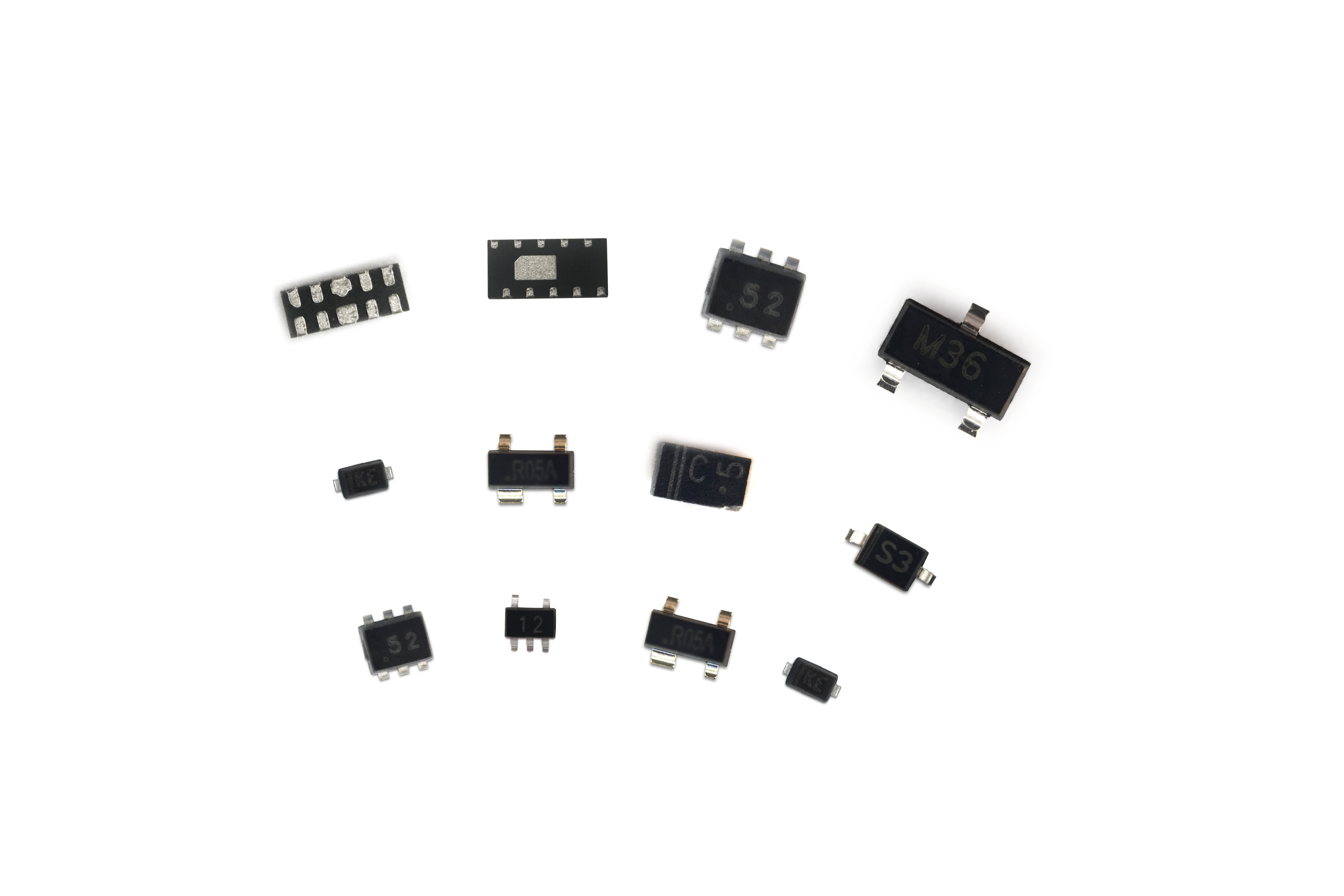
Use an isolated power supply design (isolation voltage ≥ 5kV) for sensitive equipment (e.g., monitors), and install TVS diodes (transient voltage suppression) on signal interfaces
Add a low-pass filter to the output of high-interference equipment (e.g., electrosurgical units) to suppress high-frequency harmonic radiation
10. Display systems (e.g., LCD screens) in medical equipment EMS generate electromagnetic radiation during operation. How can this radiation be reduced to comply with EMC standards?
Answer: Electromagnetic radiation from liquid crystal displays (LCDs) primarily comes from the backlight inverter (high-frequency switching, 50kHz-1MHz) and the driver circuit (clock signal from the timing controller, 10-100MHz). This radiation must be controlled through circuit design, shielding, and layout.
Measures to Reduce Radiation
Reduce the switching frequency: Reduce the switching frequency of the backlight inverter from 1MHz to 200kHz (avoiding sensitive frequency bands). Simultaneously, employ soft switching techniques (such as ZVS) to reduce dV/dt.
Clock Signal Processing: Impedance-match the driver chip's clock line (such as an LVDS signal) by connecting a 50Ω resistor in series to reduce signal reflection and radiation.
The inverter module is individually enclosed in a metal shielding box (made of galvanized steel, ≥0.2mm thick). The shielding box and the instrument chassis are grounded at multiple points.
Shielded flat cables (wrapped in aluminum foil and grounded at both ends) are used instead of standard cables for the display and driver board.
Driver circuits (such as inverters and timing chips) should be compactly laid out, with clock and power lines kept short and straight (< 3cm in length) to minimize the area of the radiation loop.
Complete ground plane: A complete ground plane (≥ 90% coverage) should be laid underneath the PCB layer where the driver circuits reside to absorb radiated energy.
Add an LC filter (L = 10μH, C = 100nF) to the inverter power input to suppress conducted interference.
Connect a 10pF ceramic capacitor in parallel (to ground) at the display interface to filter out high-frequency clock radiation.
These measures can reduce the display's radiated emissions to ≤40dBμV/m in the 30MHz-1GHz frequency band, meeting the Class B requirements of IEC 60601-1-2.
11. What potential risks might the EMS of medical devices pose to patients when subjected to electrostatic discharge? How should the EMS be designed to ensure patient safety?
Answer: The impact of electrostatic discharge (ESD) on the EMS of medical devices may indirectly or directly harm patients. Specific potential risks and protective measures are as follows:
Instrument Malfunction: Such as sudden stoppage of an infusion pump, false triggering of a defibrillator, or abnormal ventilator parameters, which may lead to treatment interruption or erroneous treatment (e.g., overdose, false shock triggering).
Signal Distortion: Bioelectric detection equipment (e.g., ECG monitors) may falsely report abnormal heart rates after being affected by ESD, leading to misdiagnosis or overtreatment.
Direct Electric Shock: If ESD is transmitted to the patient (especially for users of implantable devices) through the device casing or electrodes, it may cause localized electric shock or physiological stress reactions (e.g., arrhythmias).
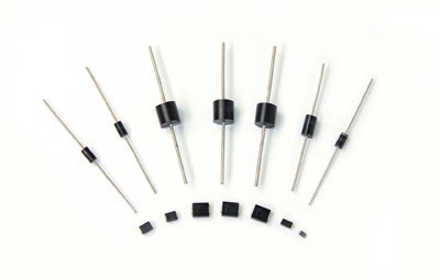
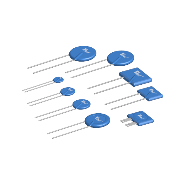
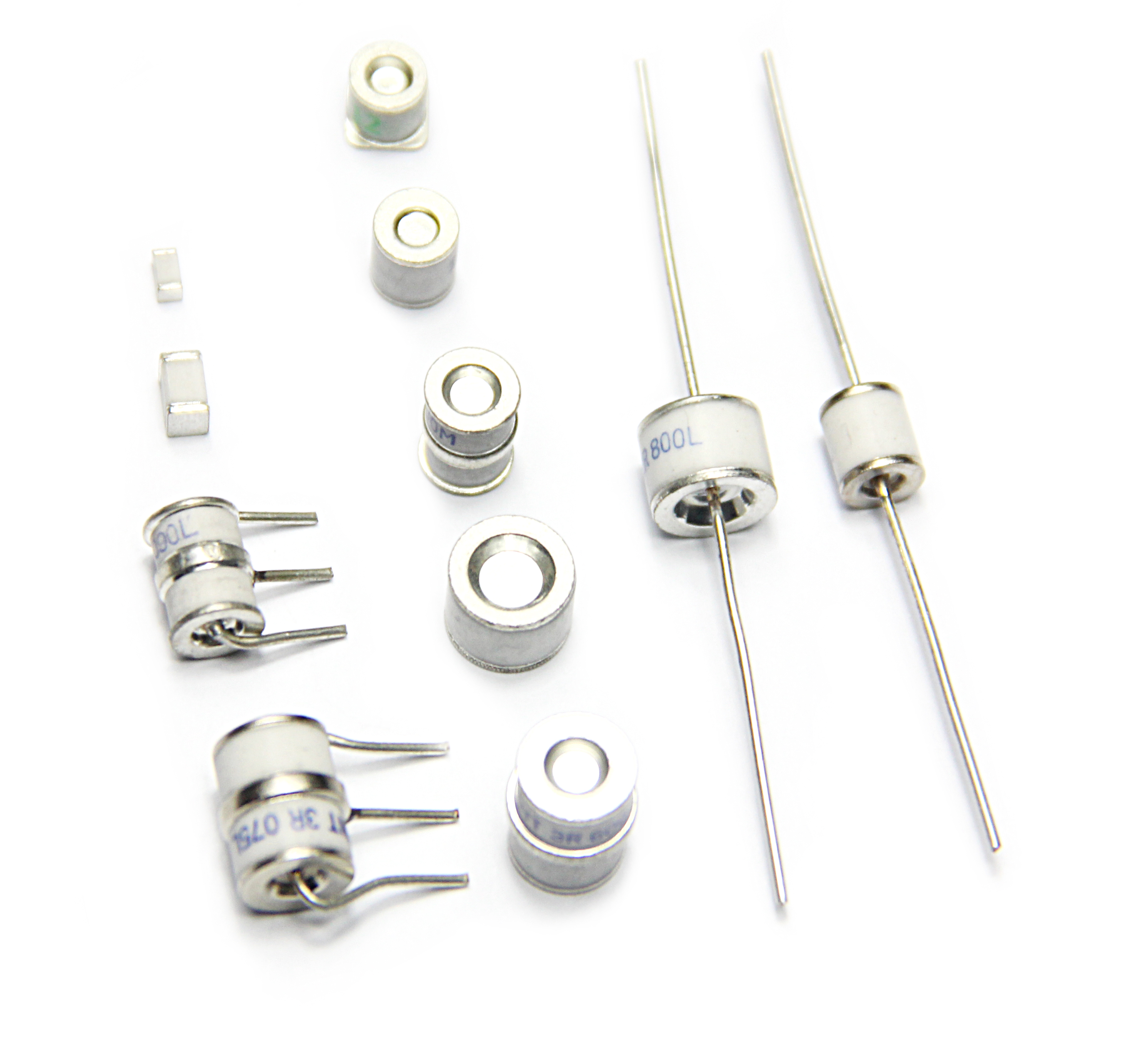
Hardware Protection: Transient suppression devices such as TVS diodes and varistors are connected in series to the interface circuit to quickly dissipate ESD energy. Critical circuits (e.g., electrode input circuits) utilize isolation designs (e.g., optocouplers, isolation transformers) to block discharge paths.
Structural Design: The device casing should be made of conductive materials (e.g., nickel-plated plastic) and reliably grounded to form a "Faraday cage." Shielding; antistatic coating on the operating panel reduces charge accumulation during human contact.
Standard Compliance: Strictly adheres to the ESD immunity requirements of IEC 60601-1-2 (±8kV for contact discharge, ±15kV for air discharge), ensuring normal operation or safe operation (such as fail-safe mode) under extreme conditions.
12. How is the performance of microelectromechanical system (MEMS) sensors in medical device EMS affected by electromagnetic interference (EMI)? How can they be protected?
Answer: MEMS sensors (such as pressure sensors and accelerometers) are extremely sensitive to electromagnetic interference (EMI) due to their micron-scale miniaturization. The specific impacts and protective measures are as follows:
Measurement Error: Electromagnetic radiation may interfere with the capacitance/piezoelectric signals within the MEMS, resulting in measurement errors for parameters such as blood pressure and flow (e.g., errors exceeding 5%).
Signal Drift: High-frequency EMI may cause the MEMS resonant frequency to shift, resulting in dynamic response delays (e.g., hysteresis in respiratory monitoring sensors).
Functional Failure: Strong electromagnetic pulses may penetrate the MEMS insulation layer, causing permanent damage (e.g., failure of the position sensor in a minimally invasive surgical robot).
Shielding Design: Add a metal shield (such as copper or Permalloy) to the MEMS sensor and connect it to a single ground point to block radiation coupling paths. Fill the gap between the shield and the sensor housing with absorbing material (such as ferrite) to absorb high-frequency interference.
Circuit Filtering: Connect an RC low-pass filter in series with the sensor output (with a cutoff frequency designed based on the signal bandwidth, such as 1kHz for a heart rate sensor) to suppress high-frequency noise. Use an LDO on the power supply. Voltage regulators reduce power supply noise coupling.
Optimizing selection: Prioritize MEMS devices with integrated EMI protection features (such as built-in shielding or differential output structures) to reduce susceptibility to external interference.
13. For mobile medical devices (such as portable ultrasound equipment and ECG monitors), how can their EMS maintain good electromagnetic compatibility during movement?
Answer: When portable medical devices (such as portable ultrasound and ECG monitors) are in motion, factors such as cable sway, environmental electromagnetic fluctuations, and unstable grounding can compromise EMC performance. The following optimizations are necessary:
Sensor cables and power cables should utilize a multi-layer shielding design (e.g., inner insulation layer + aluminum foil + braided mesh). Both ends of the shielding layer should be grounded 360° (using metal rings for crimping) to reduce electromagnetic coupling during movement.
Cable lengths should be minimized to prevent redundant cables from forming "antennas." Critical cables (such as ultrasound probe cables) should be coated with ferrite rings to suppress high-frequency radiation.
The instrument housing should be constructed of lightweight conductive materials (e.g., aluminum alloy) and connected to the internal circuit ground plane via elastic conductive pads to ensure ground continuity during movement.
Internal modules (e.g., motherboard, power supply) should be secured with anti-vibration brackets to minimize contact problems caused by vibration (e.g., EMI leakage from loose connectors).
The power module should utilize a switching power supply with a wide input range (e.g., 100-240V AC) and a built-in EMI filter (common-mode inductor + X/Y capacitors) to mitigate interference from power grid fluctuations.
Install isolation chips (such as the ADuM series) on signal interfaces (such as USB and Ethernet) to prevent interference introduced by external ground potential differences through cables.
14. How can the power management system in a medical device EMS meet the power requirements of the device while minimizing the impact of electromagnetic interference on other circuits?
Answer: The power management system is a major source of EMI (switching noise, ripple, etc.) in medical devices. It must meet power requirements while suppressing interference. Key design considerations include:
Select low-noise power devices, such as synchronous rectifier MOSFETs (on-resistance <10mΩ), to reduce noise caused by switching losses; use soft-switching controllers (such as LLC resonant topology) to reduce the dv/dt and di/dt of the switching transistors, thereby reducing radiation.
Prefer power ICs with integrated EMI optimization features (such as TI's TPS62130, which has a built-in spread-spectrum clock to disperse the noise spectrum).
Add multiple EMI filters: Add a common-mode inductor (10-100mH) and an X-capacitor (0.1-1μF) in series on the input to suppress conducted emissions; and connect a ceramic capacitor (10-100nF) and an electrolytic capacitor (10-100μF) in parallel on the output to filter ripple.
Minimize power paths: PCB In the layout, power devices such as switches, freewheeling diodes, and inductors should be placed close together to form a "small loop" to reduce the radiation area. The power ground and signal ground should be connected at a single point using a 0Ω resistor or ferrite bead to prevent noise from entering the signal circuit.
15. When the communication modules (such as Bluetooth and Wi-Fi) in the EMS of medical devices communicate with external devices, how can electromagnetic interference prevent communication interruptions or data errors?
Answer: Communication modules like Bluetooth and Wi-Fi are susceptible to EMI (e.g., data loss and interruptions), requiring coordinated hardware and software protection.
Antenna Design: Place the antenna at the edge of the instrument (away from interference sources like power supplies and motors). Use a built-in PCB antenna or a shielded external antenna (e.g., a ceramic antenna with a metal shield) to reduce interference coupling.
Signal Filtering: Connect a ferrite bead (e.g., impedance ≥ 100Ω at 100MHz) in series with the power supply of the communication module and a TVS diode (e.g., SMAJ33A) in parallel with the data line to suppress transient interference.
Interference Mitigation Algorithm: Use frequency hopping technology (e.g., Bluetooth Adaptive Frequency Hopping (AFH)) to avoid known interference bands. Add a CRC checksum (e.g., a 16-bit CRC) to data frames to trigger retransmission when an error is detected.
Redundancy Design: Use dual-path transmission for critical data (e.g., simultaneous Bluetooth and Wi-Fi backup) to ensure data is not lost if a single link is affected by interference.
16. What impact does the housing material of medical devices have on the electromagnetic compatibility of EMS? How do I choose the right enclosure material to meet EMC requirements?
Answer: The enclosure material directly affects electromagnetic shielding effectiveness (SE) and should be selected based on the application requirements.
Metals (aluminum, stainless steel): High SE (≥60dB at 100MHz), but heavy and expensive, making them suitable for fixed equipment (such as MRI consoles).
Conductive plastics (with added carbon fiber/metal powder): Moderate SE (30-50dB at 100MHz), lightweight, and easy to mold, making them suitable for portable equipment (such as handheld ultrasound systems).
Composite materials (plastic + metal coating): Adjustable SE (≈40dB for a coating thickness of 5-10μm), balancing cost and performance, making them suitable for general-purpose equipment.
Compliance with Standard Requirements: According to IEC 60601-1-2, enclosures must meet SE requirements in the 30MHz-1GHz frequency band. Requires ≥30dB (≥40dB for protection-grade equipment)
Applicable Scenarios: Metal materials are preferred for operating room equipment (to resist strong interference); conductive plastics are preferred for portable equipment (to reduce weight); avoid metal for sterilizable equipment (chemical disinfection may cause corrosion); corrosion-resistant conductive plastics should be selected.
Grounding: The outer casing must be connected to the internal ground plane via conductive adhesive or springs to ensure a closed shielding loop.
17. Does electromagnetic interference in medical device EMS affect stored data (such as patient diagnostic data)? How can data loss or corruption be prevented?
Answer:EMI can cause corruption or loss of stored data (such as patient diagnostic records). Preventive measures are as follows:
Temporary Interference: High-frequency EMI can cause RAM data to flip (e.g., accidentally writing a 0 to a 1), causing program corruption.
Permanent Damage: Strong electromagnetic pulses (e.g., lightning strikes) can damage Flash memory, rendering data unreadable.
Hardware Isolation: Storage modules (e.g., SSDs, EEPROMs) are individually shielded (grounded metal covers) and kept ≥5cm away from power and RF circuits to reduce coupling.
Data Protection Mechanisms
Use ECC memory (error correction code) to automatically repair single-bit errors.
Regularly back up critical data to non-volatile storage (e.g., SD cards) and encrypt the stored data (AES-256) to prevent tampering.
Design a "power-off protection" circuit (supercapacitor + backup power supply) to ensure data integrity during a power outage.
18. How can the electromagnetic radiation safety of medical device EMS be assessed for surrounding medical personnel and patients? What are the relevant standards and regulations?
Answer:: The assessment must ensure that radiation does not pose a health risk to medical staff and patients. The details are as follows.
Field Strength Measurement: Use a spectrum analyzer and near-field probe to measure the electromagnetic radiation field strength 30 cm from the instrument surface (electric field ≤ 6 V/m, magnetic field ≤ 0.1 A/m, 30 MHz-3 GHz frequency band).
Human Exposure Assessment: Calculate the Specific Absorption Rate (SAR) to ensure compliance with the International Commission on Non-Ionizing Radiation Protection (ICNIRP) limit (public exposure ≤ 0.08 W/kg, whole-body average).
Long-Term Effect Verification: Use accelerated aging tests to simulate the cumulative effects of long-term radiation on human tissue (such as cellular heating).
IEC 60601-1-2: Generic EMC standard for medical devices, which specifies radiated emission limits (e.g., ≤ 54 dBμV/m for Class B devices in the 30-1000 MHz frequency band).
EN 55011: Radiation exposure standards for Industrial, Scientific, and Medical (ISM) equipment, which sets radiation limits for high-frequency therapeutic devices (such as radiofrequency ablators).
FDA 21 CFR Part 1020: The U.S. Food and Drug Administration's mandatory requirements for electromagnetic radiation from medical devices, emphasizing patient safety thresholds.
Through these assessments and compliance with these standards, we ensure that electromagnetic radiation from medical devices remains within safe limits.

