Views: 0 Author: Site Editor Publish Time: 2020-10-05 Origin: Site


As the integration level of integrated circuits becomes higher and higher, the circuits become more and more complex, the operating voltage becomes lower and lower, and the requirements for environmental stability are also higher.
On the one hand, due to the high integration of the internal structure of electronic equipment, the level of withstand voltage and overcurrent resistance of the equipment is reduced, and the ability to withstand overvoltage and overcurrent is reduced. On the other hand, due to the increase in signal source paths, the system is more vulnerable Overpressure and overcurrent intrusion.
Due to the increasing competition in the telecommunications and industrial control industry, the demand for high-reliability network equipment provided by telecommunications equipment suppliers and communication product suppliers has also increased relatively. The hazards of overvoltage andarious static electricity are usually caused by: lightning strikes, induction caused by nearby wires, direct contact with power lines, or user equipment failures. These hazards may endanger telecommunications network equipment users and maintenance personnel. Therefore, telecommunication equipment suppliers have increased the equipment's ability to resist overvoltage and overcurrent to reduce system maintenance costs and improve the reliability.
● Comply with IEC61000-4-2 (ESD): Air-15kV, Contact-8kV
● Conform to IEC61000-4-4 (EFT): 40A-5 / 50ns
● Comply with IEC61000-4-5 (Surge): 24A, 8 / 20µs-Level 2 (Line-Ground) & Level 3 (Line-Line)
● Low junction capacitance: 3pF Typical
● RoHS compliant
● Simple and convenient design
10 / 100M Ethernet port Applicable conditions: Use a network cable to connect the device that is less than 10M away from the fully exposed direct lightning zone
Test standard: TU-T K.21 (10/700 μS) Impedance (40Ω) Differential mode: 1.0KV Common mode: 6.0KV

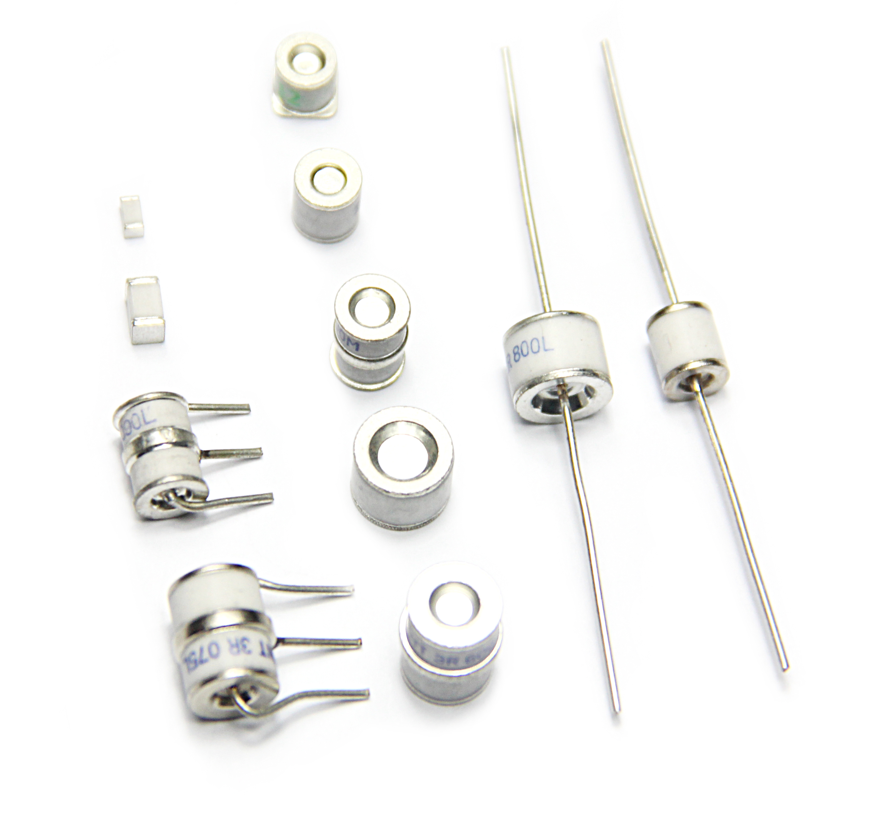
| Device Selection | GDT | ESD |
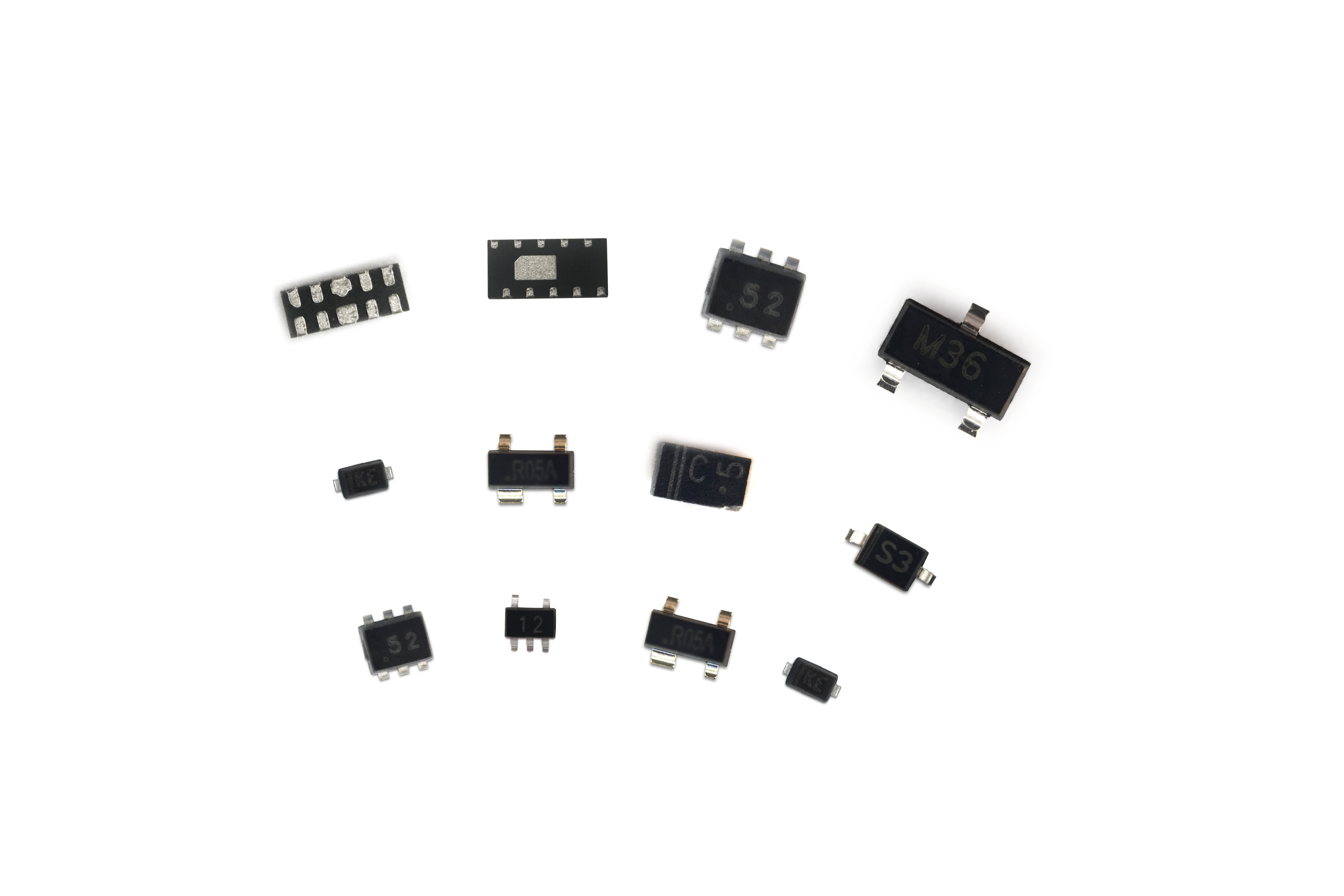
| GDT/SMD1812-091 | ESDLC3V0D3 | |
| Package | SMD 1812 | SMD SOD-323 |
| Parameters | 8/20uS Throughou Current 2KA | 3.3V Clamping Voltage 5.15V |

| Device Selection | GDT | ESD |
| INT3R090L-8 | ESDSRVLC05-4 | |
| D: 5.5mm | INT3R090L-5.5 | ESDSRVLC05-4 |
Note: The resistance of R1 ~ R4 is called BST (Bob Smith Terminal) .The purpose is to match the impedance between two pairs of twisted pairs, which is conducive to signal transmission and greatly helps electromagnetic radiation.

| Device Selection | GDT | ESD |
| GDT/SMD1812-091 | ESDLC3V0D3B |
The scheme chooses the first stage to use a GDT gas discharge tube to discharge the surge current to the ground through a switch-type gas discharge tube, or the inert gas arc of the discharge tube electrode is eliminated in the form of heat.In the middle, the inductance characteristics of the network transformer are fully utilized to play the role of decoupling and isolation.The second stage uses ESD devices, which can absorb the residual frequency component surge, and the clamping voltage is reduced to about 8V under IPP, so that the Ethernet chip is in a safe protection state!
For POE power, the international IEEE 802.3 standard description and two power methods
IEEE 802.3af Power classification of PSE and PD
| Use | Lowest Power Output Level On PSE | Maximum power level on flashlight equipment |
| Default | 15.4W | 0.44 to 12.95 W |
| Optional | 4.0W | 0.44 to 3.84 W |
| Optional | 7.0W | 3.84 to 6.49 W |
| Optional | 15.4W | 6.49 to 12.95 W |


INT.P0640SCL + PPTC Protect POE
SMCJ58A + PPTC Protect POE
The effect of TVS diodes and semiconductor discharge tubes (thyristor)