Views: 0 Author: Site Editor Publish Time: 2023-11-07 Origin: Site

It can be used in situations where the signal frequency/transmission rate is low, there may be continuous DC voltage in the line, and the surge current is small. When the grounding wire is long and the signal is susceptible to interference, add a TVS tube or glass discharge tube with a breakdown voltage greater than 100V and then ground it.

It can be used in situations where the signal frequency/transmission rate is low, there cannot be continuous DC voltage in the line, and the surge current is small. When the grounding wire is long and the signal is susceptible to interference, add a TVS tube or glass discharge tube with a breakdown voltage greater than 100V and then ground it.

+24V negative ground power supply, additional resettable fuse, discharge tube voltage = 2*signal voltage, TVS tube or glass tube = 1.2*signal voltage

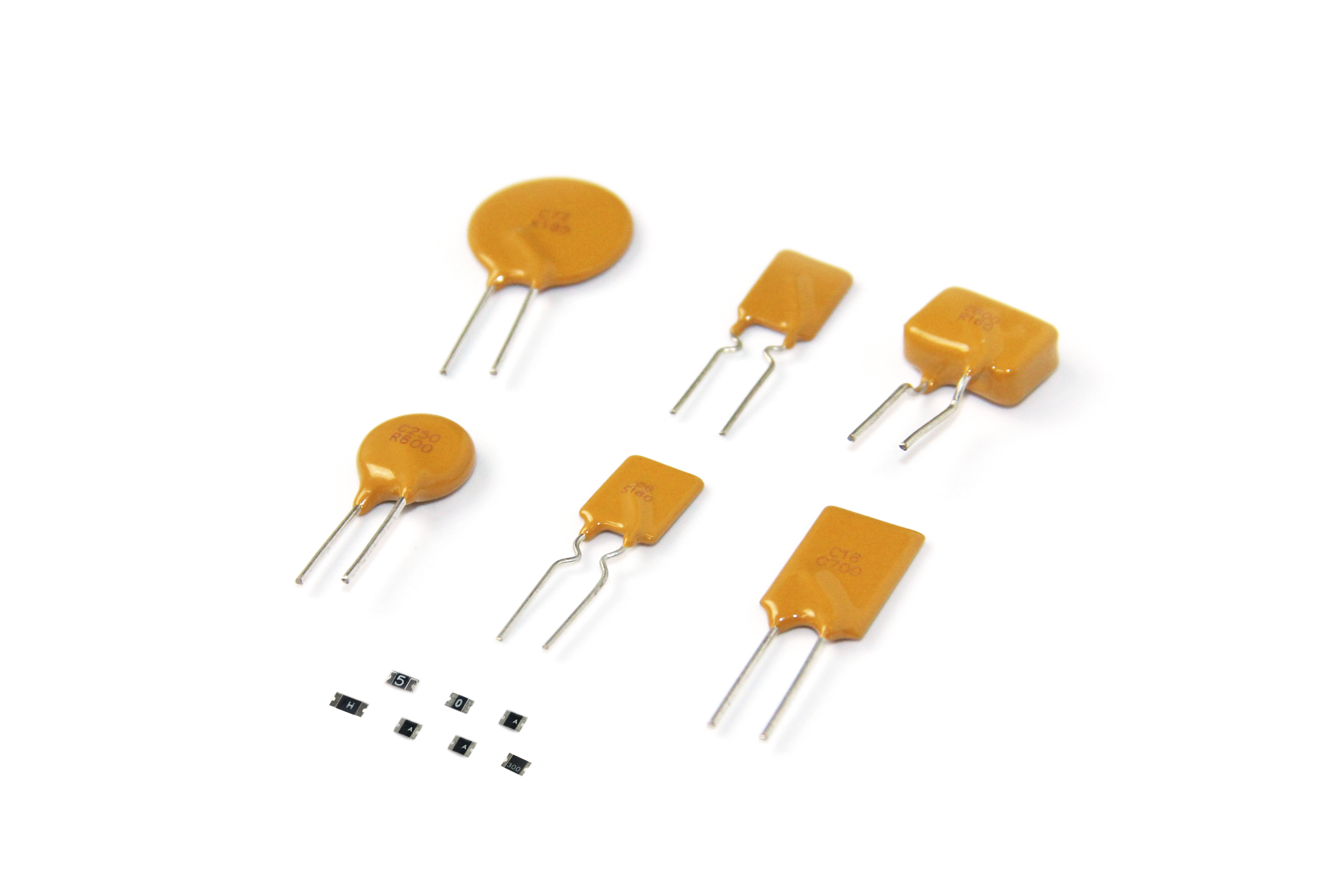
①R1, R2 metal oxide film resistors (2W-4.3~5.1Ω), you can also use positive temperature coefficient thermistors with equivalent cold resistance (such as: self-restoring fuse: LP60-010/030, LB180 (U));
②The DC breakdown voltage of ceramic gas discharge tubes and semiconductor overvoltage protectors (only applicable when there is no continuous DC voltage in the circuit) is selected according to the signal voltage amplitude;
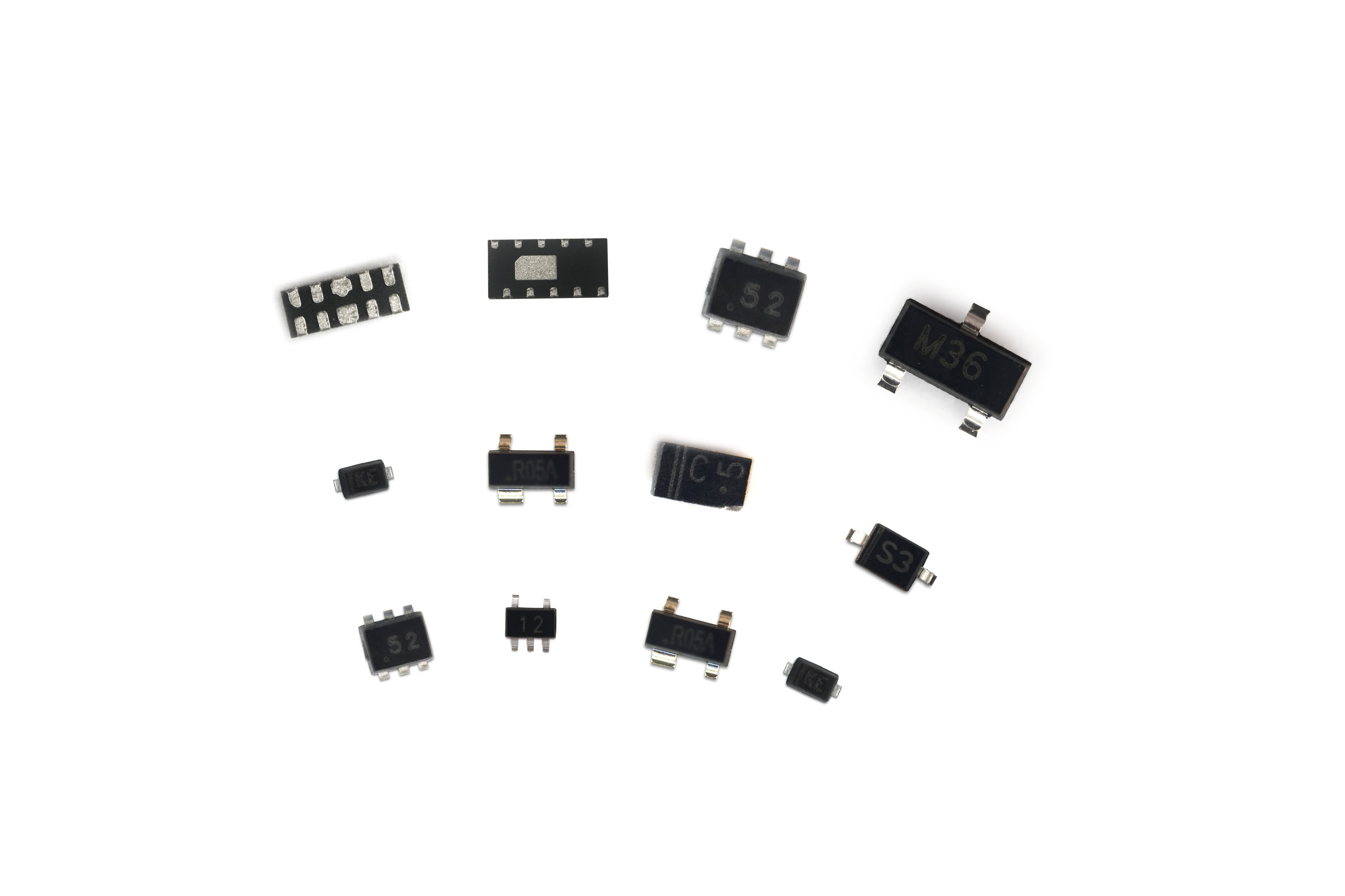
③This circuit is suitable for transmitting high-frequency/high-speed signals (the highest frequency can reach 20MHZ). Use low capacitance TVS diodes or semiconductor overvoltage protectors. Transmission frequency/rate ≥10MHz, Cj≤60pF; Transmission frequency/rate ≥100MHz, Cj≤20pF;
① The protection effect is very good, the residual voltage is low, and power can be transmitted at the same time. It is suitable for antennas with or without amplifiers.
②The cavity and input and output connectors are specially designed and processed according to the type of connectors used in the system and the frequency range of the transmission signal. When used outdoors, the cavity, joints and covers must be designed to be waterproof.
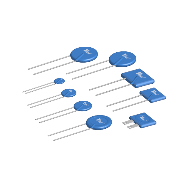
③Ceramic gas discharge tubes are generally selected with a flow capacity of 20kA and a DC breakdown voltage of 90V, and the varistor is generally selected as 20D100K type;
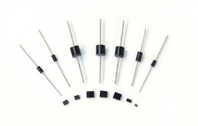
The breakdown voltage of TVS tube is selected according to the transmission DC voltage or AC voltage peak value (VBRmin≥1.2UDC or VBRmin≥1.2Up).
④C is a flat capacitor made of copper sheets, with a polytetrafluoroethylene film between the flat plates; L1 and L4 are hollow inductors wound with enameled copper wire, and L2 and L3 can use core inductors of about 100 μH.
⑤ After installing the components into the cavity, use a microwave network analyzer to test the standing wave coefficient and insertion loss within the signal frequency range, which should meet the requirements.

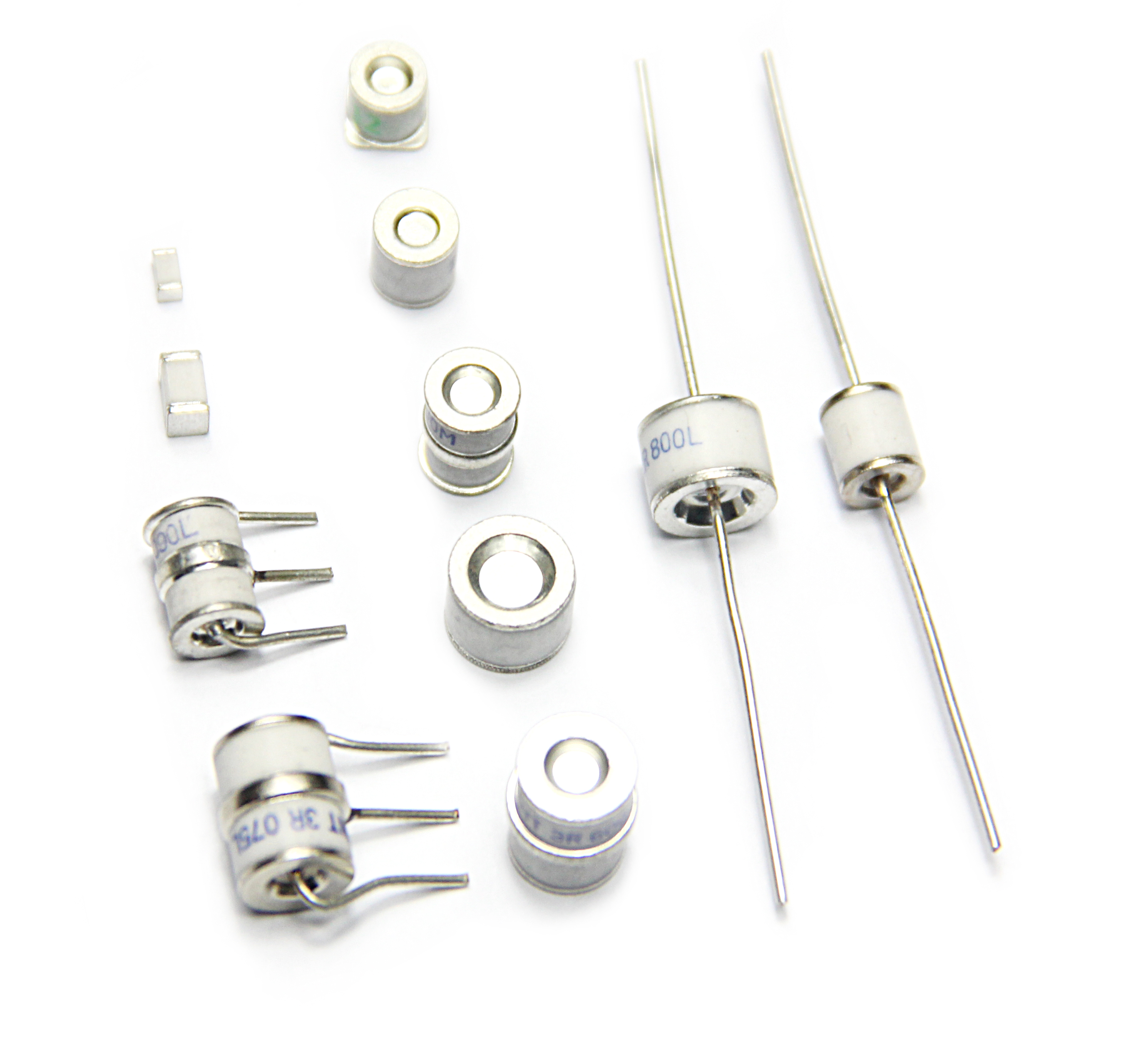
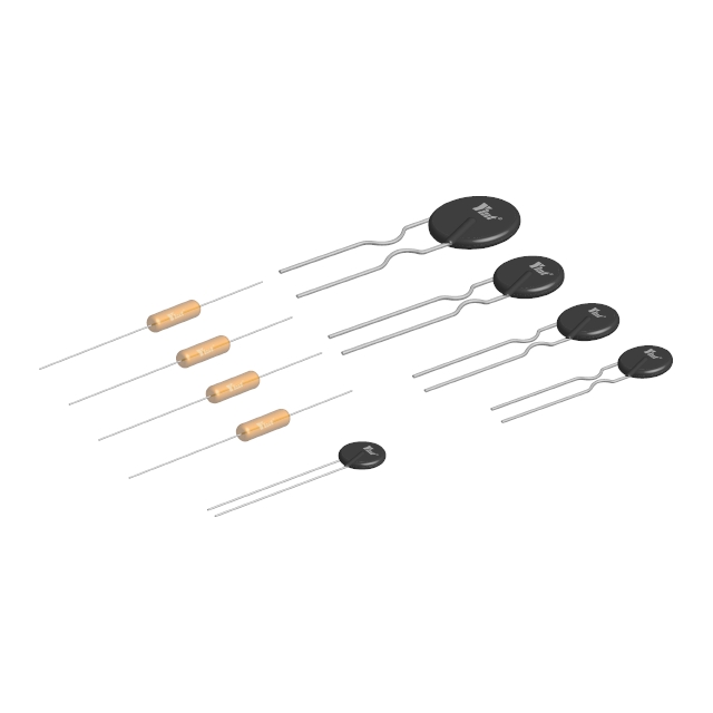
Ceramic gas discharge tube is the most widely used switching device in lightning protection (surge) protection equipment. It can be used to discharge lightning current whether it is lightning protection for AC or DC power supplies or lightning protection for various signal circuits. into the ground. Its main characteristics are: large discharge current, small inter-electrode capacitance (≤3pF), high insulation resistance (≥10GΩ), large breakdown voltage dispersion, and slightly slower reaction speed. According to the number of electrodes, there are two types: diode discharge tubes and three-pole discharge tubes (equivalent to two diode discharge tubes connected in series, with the common contact grounded). Its appearance is cylindrical, and it has two structural forms: with leads and without leads.
①DC breakdown voltage VSdc: The breakdown voltage value when a DC voltage of 100V/s is applied to the discharge tube. This is the nominal voltage of the discharge tube. Commonly used ones include 75V, 90V, 150V, 230V, 350V, 470V and 600V, 800V, 1500, 2500, 3KV, etc. The error range: generally ±20%.
②Pulse (impulse) breakdown voltage VSP: The breakdown voltage value when a pulse voltage of 1kV/μs is applied to the discharge tube. Due to the slow reaction speed, the pulse breakdown voltage is much higher than the DC breakdown voltage.