Home
CN
Products
EMS Products
TVS Diodes
ESD Protection Diodes
Resettable Fuses
Thyristor Surge Suppressor
Gas Discharge Tubes
Schottky Barrier Diodes
Varistors
NTC thermistors MF72
eFuse
NTC thermistors MF52、MF58
EMI Products
Common Mode Choke
Power Inductors
Ferrite Beads
Common-mode Chokes for CAN FD
Sensors
Temperature sensor devices
Temperature sensor module
Power Devices
MOSFET
Rectifier Diodes
Zener Diodes
Surge Protective Device
SPD for Power Supply
SPD for Signal
SPD for Power + Signal
SCB
Applications
Industrial
Medical & healthcare
Automotive
Energy infrastructure
Consumer electronics
Electronic detonator
Client Cases
Development
Industry Layout
Patent Qualifications
Production Management
Product Planning
Our Future
News & Events
Corporate News
Industry News
Product Knowledge
Training & Education
About
Company Profile
Cultural Philosophy
Organizational Structure
Development History
Sales Network
Honors and Certifications
Contact Us
Support
Sample Request
Technical Support
EMC/CNAS Test
FAQ
Cross-reference search
Careers
Career Development
Employee Culture
Benefits and Compensation
Search jobs
Global
CN
Home
Products
EMS Products
EMI Products
Sensors
Power Devices
Surge Protective Device
Cross-reference search
TVS Diodes
ESD Protection Diodes
Resettable Fuses
Thyristor Surge Suppressor
Gas Discharge Tubes
Schottky Barrier Diodes
Varistors
NTC thermistors MF72
eFuse
NTC thermistors MF52、MF58
Common Mode Choke
Power Inductors
Ferrite Beads
Common-mode Chokes for CAN FD
Temperature sensor devices
Temperature sensor module
MOSFET
Rectifier Diodes
Zener Diodes
SPD for Power Supply
SPD for Signal
SPD for Power + Signal
SCB
Applications
Industrial
Medical & healthcare
Automotive
Energy infrastructure
Consumer electronics
Electronic detonator
Industrial Connectivity and Communication
Industrial automation
Industrial motion and drive
Sensing and Human machine interface (HMI)
Lighting
PLC IoT gateway
Power line Carrier
HMI
PLC
Industrial controller I/O system
Inverter for motion control system
Servo drive for motion controller
Industrial alarm devices
Sensors
Smart lights
Landscape lights
Diabetes healthcare
Hospital patient care
In-vitro diagnostics
Blood glucose monitor
Dental medical equipment
Oxygen concentrator
Blood pressure monitor
Pulsating pulse oximeter
Comprehensive diagnostic and treatment equipment for tinnitus and hearing loss
Infusion pump
Electronic chair
Electronic bed
CPAP ventilator
Electrocardiogram (ECG)
Portable blood coagulation analyzer
Semi-automatic thromboelastography
Immunoassay analyzer
Fecal analyzer
Flow cytometer
Molecular analyzer
Advanced driver assistance systems (ADAS)
Body electronics
Car access & security systems
Car access & security systems
Lighting
Infotainment & cluster
Car entertainment system
Power supply
In-cabin camera module
Mirror replacement/camera mirror system
Front camera
Rear door module
Wiper module
Kick to open module
PEPS
Heat pump module
Interior light
Headlight Adaptive LED Driver Module
Headlight HB/LB LED Driver Module
Small light
Rear light
Zone control module
Domain gateway
Automotive USB charging
Premium audio
Automotive display
Onboard battery charger
12V/48V power distribution box
48V New Energy System
Energy storage systems
Charging pile
Smart meter
Smart circuit breakers
Grid automation
Micro inverter
Uninterruptible power supply
Battery management system (BMS)
DC charging (pile) station
AC charging (pile) station
Gas meter
Electricity meter
Water meter
Smart electrical panel
Solid state circuit breaker (SSCB)
Industrial circuit breaker
GFCI/RCD circuit breaker
DFCI circuit breaker
AFCI circuit breaker
Fault indicator (FI)
Power quality meter
Power quality analyzer
Grid asset monitoring
High-voltage direct current (HVDC) power transmission
Personal computing and entertainment
Smart Home and IoT
Personal travel and drones
Power and charging
VR glasses
Desktop computer
Smart parcel lockers
Smart lock
Two-wheeled vehicle tracker
E-BIKE
Drone
PD
Electronic detonator
Electronic detonator
Support
Support
With over a thousand cooperative customers and 17 years of service experience, we can provide you with everything from model selection to technical support
Sample Request
Technical Support
EMC/CNAS Test
FAQ
Cross-reference search
Development
Development
Our unyielding mission is to continuously innovate and lead the industry's progress.
Industry Layout
Patent Qualifications
Production Management
Product Planning
Our Future
News & Events
News & Events
We will share every little bit of our life with you at all times
Corporate News
Industry News
Product Knowledge
Training & Education
About
About
Yinte Electronics integrates technology research and development, chip manufacturing, packaging and testing, sales, and service
Company Profile
Cultural Philosophy
Organizational Structure
Development History
Sales Network
Honors and Certifications
Client Cases
Contact Us
Careers
Careers
Unleash potential together, shape a healthy future for humanity
Career Development
Employee Culture
Benefits and Compensation
Search jobs
Select model to search
|
Cross-reference search
Online Message
Name
*
Company
Email
*
Phone
Message
Contact
News & Events
We will share every little bit of our life with you at all times
Corporate News
Industry News
Product Knowledge
Training & Education
News & Events
We will share every little bit of our life with you at all times
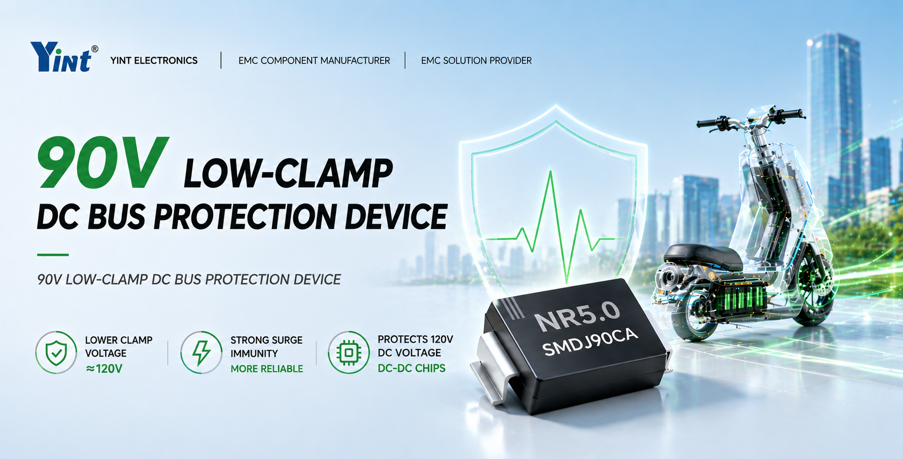
90V DC Bus Low-Clamping TVS Surge Protection Solution|120V Withstand DC
2026-05-14
NR5.0SMDJ90CA low clamping TVS diode protects 90V bus systems, clamping surges near 120V to prevent DC-DC chip breakdown and latent failure.
Explore More
What are the Main Parameters of Common Mode Filters? Usage Precautions? How to Use in Solar Inverters?
2023-06-13
Main parameters: 1. Common mode rejection ratio: Indicates the ratio of the filter's impedance to common mode signals and differential mode signals. 2. Passband: Indicates the degree to which the filter passes differential mode signals within a certain frequency range. 3. Cutoff frequency: Indicates the degree to which the filter suppresses common mode signals; the smaller the value, the stronger the suppression of high-frequency common mode signals. 4. Phase balance: During filter operation, phase balance of the two signals must be ensured to avoid suppression of differential mode signals. Precautions: 1. The installation position of common mode filters should be as close as possible to the signal source and load end to minimize transmission of common mode signals. 2. To reduce electromagnetic interference, the input and output of common mode filters should use the same type of connection as much as possible, such as two BNC connectors or two plug connectors. 3. The wiring method of common mode filters should follow the correct wiring sequence and steps to ensure normal operation and long-term use of the filter. How to use in solar inverters: Common mode filters are often needed in solar inverters to reduce electromagnetic interference, ensuring purity and stability of output signals. Usually, filters should be installed between solar panels and inverters to reduce transmission of electromagnetic interference. Additionally, an additional common mode filter can be connected at the inverter output end to further improve filtering effect. During use, ensure the filter's passband and cutoff frequency match system requirements, and adopt correct wiring steps and sequence to ensure normal operation.
What are the Main Parameters of Zener Diodes? Usage Precautions?
2023-06-13
The main parameters of Zener diodes include rated reverse operating voltage (Vz), maximum Zener current (Izmax), maximum power dissipation (Pmax), temperature coefficient (TC), reverse leakage current (Ir), etc. Among them, rated reverse operating voltage refers to the voltage magnitude of the Zener diode during operation; maximum Zener current refers to the current limit at which the Zener diode can operate stably; maximum power dissipation refers to the maximum power the Zener diode can withstand; temperature coefficient refers to the effect of temperature changes on the operating voltage change of the Zener diode; reverse leakage current refers to the magnitude of the reverse current of the Zener diode. When using Zener diodes, the following should be noted: First, when using, appropriate Zener diodes should be selected according to the required voltage value and maximum Zener current; second, during power use, exceeding the maximum Zener current should be avoided to prevent overheating and damage of the Zener diode; third, because Zener diodes have a large temperature coefficient, the effect of temperature changes on their operating voltage should be avoided as much as possible; finally, when using, pay attention to the connection of positive and negative poles, avoid reverse connection and overload.
What are the Main Parameters of NTC Power Thermistors? Usage Precautions?
2023-06-13
The main parameters of NTC power thermistors include: rated power, rated resistance, temperature coefficient, operating temperature range, accuracy, etc. Precautions: 1. Should correctly select rated power and rated resistance according to circuit requirements. 2. The temperature coefficient should match the usage environment to achieve better temperature measurement effect. 3. The operating temperature range should meet the usage requirements of the resistor to prevent damage due to excessively high or low temperatures. 4. Protective measures should be noted to avoid influence from external factors such as moisture and contamination. 5. During use, excessive vibration and impact should be avoided to prevent damage to the resistor element.
What are the Main Parameters of ZnO Varistors? Usage Precautions?
2023-06-13
ZnO varistors are commonly used electronic components for protecting electronic equipment from excessive voltage effects. Their main parameters include: 1. Rated voltage: The maximum voltage value that the ZnO varistor can withstand under standard working conditions. 2. Rated power: The maximum power value that the ZnO varistor can withstand under standard working conditions. 3. Resistance value: The resistance value of the ZnO varistor, which may vary under different working conditions. 4. Capacitance: The capacitance of the ZnO varistor, usually smaller than that of resistors with equivalent parameters. 5. Response time: The reaction time of the ZnO varistor when encountering overvoltage. When using ZnO varistors, the following points should be noted: 1. Must select ZnO varistors that meet design requirements to ensure their normal operation and protect the stability of the equipment. 2. Select ZnO varistors with correct rated voltage and power to avoid overvoltage and electrical power exceeding device tolerance. 3. During use, avoid applying excessive peak voltage to ZnO varistors to prevent damage to the device. 4. Strictly select and install ZnO varistors according to usage site requirements, avoid excessive vibration or mechanical damage. 5. Safely store and use ZnO varistors to prevent them from encountering mechanical or chemical damage. 6. Do not touch the pins or surface of varistors with hands to avoid electrical hazards or damage to the device.
What are the Main Parameters of MOSFETs? Usage Precautions?
2023-06-13
MOSFET, full name Metal-Oxide-Semiconductor Field-Effect Transistor, is one of the commonly used power semiconductor devices. Its main parameters include: 1. Rated voltage (VDS): The maximum withstand voltage of the MOSFET. 2. Maximum current (ID): The maximum current capacity of the MOSFET. 3. On-resistance (RDS(on)): The resistance when the MOSFET is switched on. 4. Gate voltage (VGS): The gate voltage of the MOSFET, controlling its conductivity change. 5. Threshold voltage (Vth): The gate voltage at which the MOSFET becomes effective. 6. Symbol temperature coefficient (VT): The degree of change of MOSFET gate voltage with temperature, often used to measure the temperature stability of the device. When using MOSFETs, the following points should be noted: 1. Select MOSFETs with appropriate specifications and parameters to ensure their normal operation and long life. 2. Ensure the operating voltage of the MOSFET does not exceed its rated voltage, and try to avoid overvoltage and overcurrent. 3. Properly cool the MOSFET to reduce its temperature, improving reliability and lifespan. 4. Correctly select and design the drive circuit of the MOSFET to ensure normal turn-on and turn-off. 5. Avoid electrostatic discharge or mechanical damage to the MOSFET, as these factors may cause MOSFET damage or failure. 6. Correct use of MOSFET tools and instruments can help you better detect and maintain MOSFETs, ensuring long-term stability and performance of the device.
What are the Main Parameters of GDT Gas Discharge Tubes? Usage Precautions?
2023-06-13
GDT gas discharge tubes (Gas Discharge Tube) are electrical protection components used to protect electronic equipment. Their main parameters include: 1. Rated voltage: The operating voltage range of the gas discharge tube. 2. Leakage current: The leakage current of the GDT gas discharge tube under a fixed voltage. 3. Strike voltage: The voltage value at which the GDT gas discharge tube starts to discharge electricity. 4. Holding current: The current value during normal operation of the gas discharge tube. 5. Time to protection current and voltage: The reaction time under the protection current and voltage at which the gas discharge tube can ultimately activate. When using GDT gas discharge tubes, the following points should be noted: 1. The selected GDT gas discharge tube must meet design requirements and not exceed its maximum rated voltage and current. 2. Gas discharge tubes are usually installed at the entrance of the circuit needing protection to provide optimal circuit protection. 3. After the GDT gas discharge tube discharges electricity, its internal capacitor will discharge, forming instantaneous high voltage. Therefore, ground wires and guiding wires should be well maintained, and direct contact should be avoided. 4. Do not arbitrarily change the parameters of the gas discharge tube or perform disassembly and repair to avoid electrical hazards. 5. Correct selection and use of GDT gas discharge tubes can greatly improve the voltage withstand level of electronic products, reduce circuit failures, and extend the service life of electronic products.
What are the Main Parameters of TSS Thyristors? Usage Precautions?
2023-06-13
The main parameters of TSS thyristors (Transient Voltage Suppressor SCR) include: 1. Maximum peak voltage (VDRM): The maximum periodic repetitive peak voltage that the TSS thyristor can withstand. 2. Maximum controllable current (ITSM): The maximum instantaneous controllable current that the TSS thyristor can withstand. 3. Peak pulse current (IH): The instantaneous pulse current that the TSS thyristor can withstand. 4. Operating temperature range: The temperature range in which the TSS thyristor can operate stably. 5. Trigger current (ITH): The trigger current that needs to be provided to start the conduction of the TSS thyristor controlled thyristor circuit. When using TSS thyristors, the following points should be noted: 1. The TSS thyristor used must meet design requirements and not exceed its maximum rated voltage and current. 2. For the trigger circuit of TSS thyristors, power supply noise and interference must be fully considered. 3. TSS thyristors generate heat during heating, especially when used in high-temperature environments, heat dissipation should be paid more attention. 4. TSS thyristors need to be purchased through formal channels to ensure their quality and reliability. 5. When installing and operating TSS thyristors, relevant safety regulations must be followed.
https://www.yint.com.cn/products/emsproduct/tss/index.html
ESD Protection Diode Failure Modes and Usage Precautions
2023-06-13
ESD protection diodes may fail during use. Common failure modes mainly include the following: 1. Suppression circuit failure: When ESD protection diodes are excessively activated or activated too quickly, it may lead to suppression circuit failure, thus unable to protect the protected components from electrostatic discharge effects. 2. Open circuit: ESD protection diodes may fail due to excessive activation or too rapid activation, leading to an open circuit state, at which point they will have no effect on the protected components. 3. Short circuit: Some ESD protection diodes may short circuit when failing, which will cause unnecessary burden on the protected components. When using ESD protection diodes, the following should be noted: 1. Ensure the usage limits of ESD protection diodes are not exceeded, including maximum voltage, maximum current, and operating temperature. 2. Should be used according to correct pin layout, soldering, and mechanical installation guidelines to ensure stability and reliability. 3. When ESD protection diodes fail, they must be replaced immediately to maintain protective effect.
Power Classification of TVS Transient Suppression Diodes
2023-06-13
According to different voltage levels and power sizes, TVS transient suppression diodes can be classified into multiple categories. Here are some common classification methods: 1. According to working voltage level: Can be divided into low voltage (3kV) three categories. 2. According to rated power: Can be divided into low power (30W) three categories. 3. According to package type: Can be divided into different package forms such as SMD, DO-214AB, DO-15, etc. 4. According to trigger voltage: Can be divided into unidirectional and bidirectional, with bidirectional TVS diodes further divided into symmetrical and asymmetrical. 5. According to application field: Can be divided into different application scenarios such as consumer electronics, communication, automotive electronics, etc. The above classification methods are only one common classification method; actually, there are other classification methods, such as classification according to operating temperature range, reverse leakage current level, etc. The purpose of classification is to facilitate selection and application of different types of TVS transient suppression diodes to meet different needs.
总计 465
1
2
...
37
38
39
40
41
42
43
...
51
52

 Global


 沪公网安备31011702889749号
