
 Global


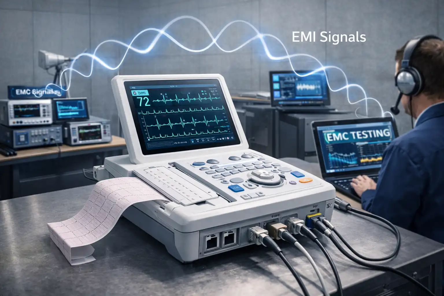
First, the electromagnetic compatibility challenges faced by medical ECG equipment.
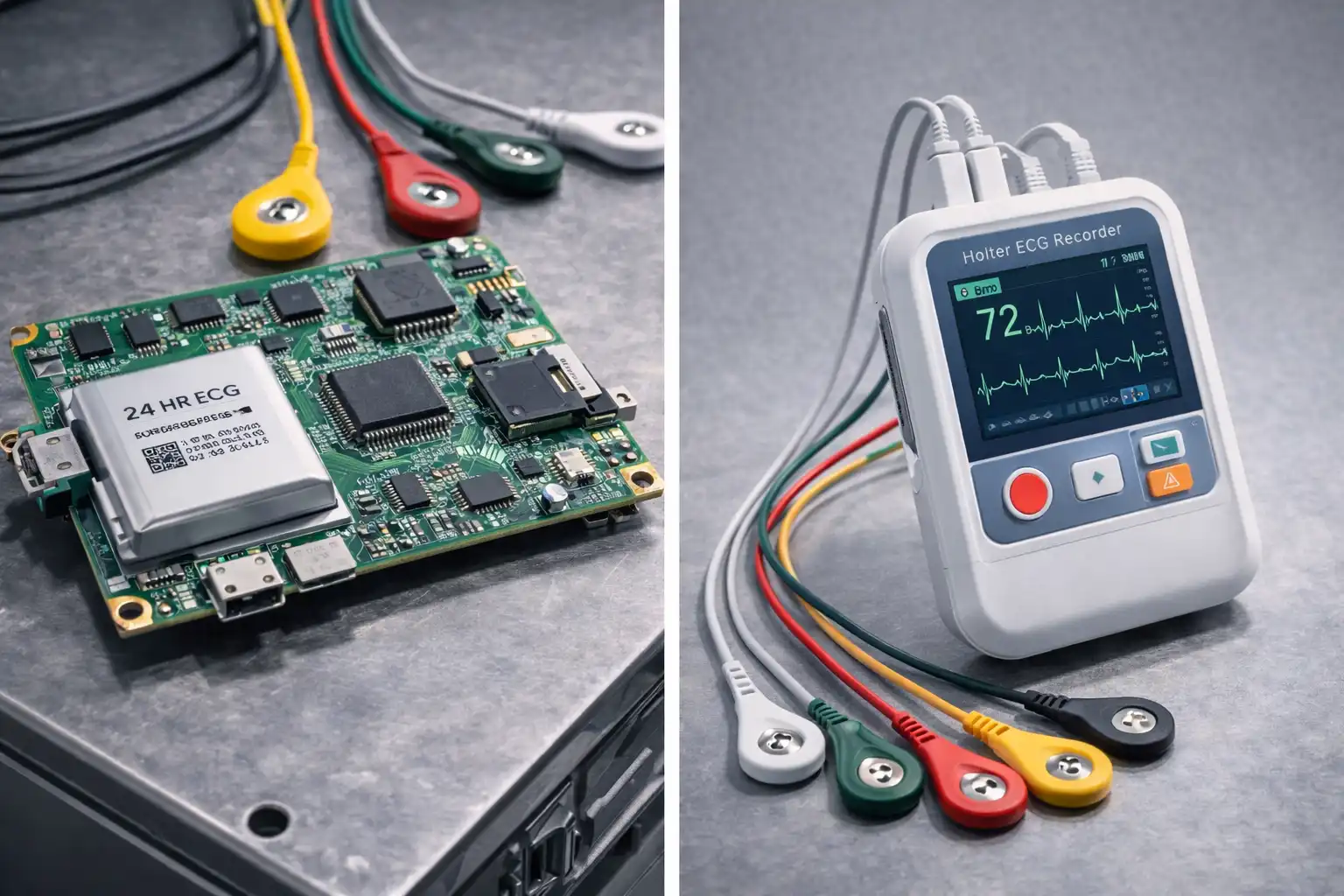
As a critical medical diagnostic device, the ECG machine's signals are extremely weak, typically at the millivolt (mV) level, making them highly susceptible to interference from both internal and external electromagnetic interference (EMI). In complex medical environments, noise can be introduced by the device's own switching power supply, nearby wireless equipment, or even electrostatic discharge (ESD) from medical staff. This can lead to distorted ECG waveforms, baseline drift, or artifacts, severely impacting diagnostic accuracy. With the trend towards portable and wireless medical devices, ECG equipment has become more integrated and operates across wider frequency bands. Consequently, its electromagnetic compatibility (EMC) design, particularly the ability to suppress conducted and radiated interference, has become a key factor determining product success.
Second, the core EMC design pain points for ECG equipment.
R&D engineers face multiple challenges in ECG design.
2.1 The primary issue is balancing signal integrity with protection capability. The front-end amplifier used for signal input requires extremely high input impedance and common-mode rejection ratio (CMRR). Any introduced parasitic capacitance can degrade high-frequency response, leading to waveform distortion.
2.2 Secondly
the equipment must meet stringent medical safety standards, such as IEC 60601-1-2, which has clear requirements for immunity tests like ESD, electrical fast transient (EFT) bursts, and surge.
2.3 Common failure modes include
ESD causing latch-up or breakdown of the analog front-end (AFE) chip; EFT noise on the power line coupling into the signal line via common-mode paths; and interference from switching noise generated by the device's internal digital circuits (such as the MCU and display) on the analog circuits. If these interferences are not handled properly, they can cause device resets at best, or permanent hardware damage at worst.
Third, building a system-level ECG protection strategy.
Effective EMC design must start from the system architecture, adhering to the fundamental principles of "shielding, filtering, and grounding." In terms of circuit topology, an isolation design should be adopted, physically and electrically isolating the analog signal acquisition section from the digital processing and power sections, for example, by using isolated power modules and digital isolators. For critical lead input lines, a two-stage protection strategy is required:
First Stage: Use ultra-low capacitance TVS arrays at the device ports to clamp common-mode and differential-mode ESD.
Second Stage: Use π-type or T-type filters before the signal enters the AFE to filter out high-frequency noise. At the power entry point, common-mode chokes (CMCC) and TVS diodes need to be deployed to suppress conducted interference from the power grid. A reasonable PCB layout is also crucial.
Special Considerations: Strictly separating analog ground from digital ground, using a complete ground plane, and keeping sensitive analog traces away from noise sources are the foundational requirements for ensuring the effectiveness of the solution.
Given the high impedance and high sensitivity characteristics of the electrocardiogram (ECG) front-end, YINT's signal interface protection solutions are particularly critical. To ensure that weak physiological signals are not degraded, it is recommended to use protection devices with "low capacitance" and "fast response" characteristics to avoid degrading the signal bandwidth. For example, for ESD protection at lead wire interfaces, the low capacitance requirement is consistent with scenarios such as automotive SENT transmission and signal MIC protection. Low-capacitance TVS diodes such as ESDLC5V0D3B or ESDLC5V0APB can be selected, with capacitance values as low as a few picofarads (pF). These provide precise electrostatic clamping voltage while having almost no impact on the signal bandwidth. For potential user contact points on the device, such as buttons, touchscreens, or SD card slots, models like ESD5V0D8B, ESD0524P, or ESDLLC5V0D8BH can be selected accordingly to achieve integrated protection for multiple signal lines, saving PCB space.
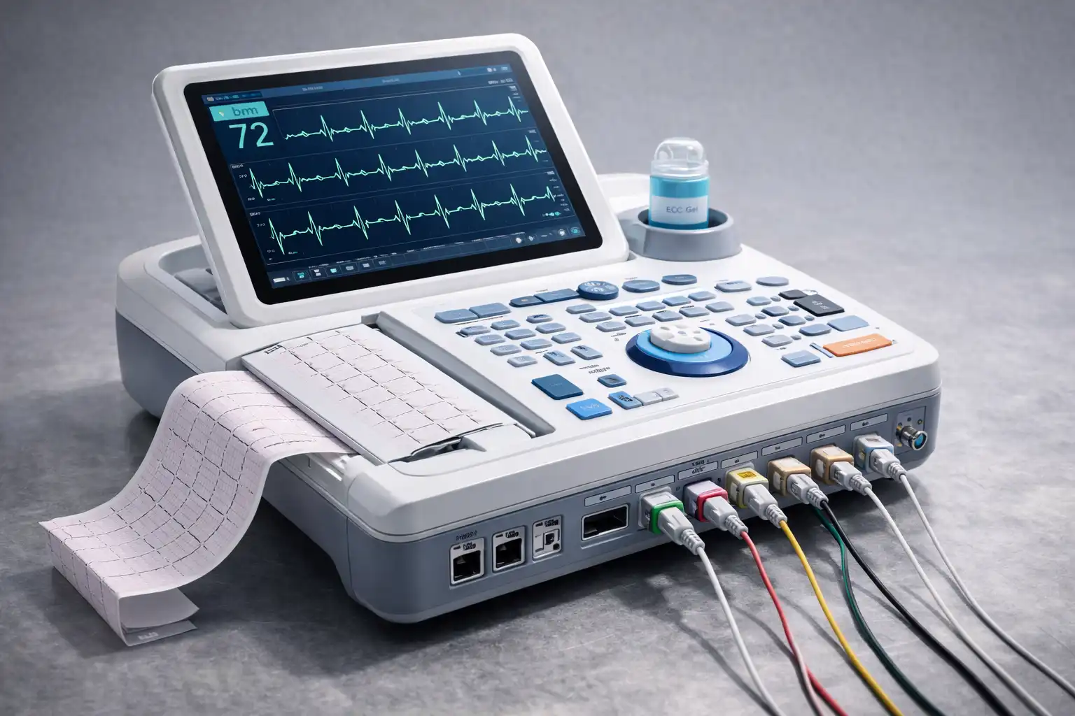
Fourth, Power and System Port Protection Solutions for ECG Machines
The power lines and system buses (such as USB or Ethernet interfaces for data transmission) of ECG equipment are the main paths for interference intrusion. For portable ECGs using 12V or 24V DC power supply, their power input terminals face surge threats. A combined protection scheme using TVS and filtering devices in coordination is recommended: First, use components like magnetic beads or common mode chokes such as `CMZA706-701T` to suppress high-frequency noise, followed by TVS diodes with strong current-handling capabilities like SMCJ24CA or 5.0SMDJ24CA for surge absorption in the subsequent stage. If the device integrates wired network functionality for data transmission, for Fast Ethernet (RJ45) interfaces, common mode chokes like CMZ3225A-900T can be selected to suppress common-mode noise on differential lines, and be paired with low-capacitance TVS arrays specifically designed for Ethernet PHY chip protection, such as ESDLC3V3D3B or ESDSLVU2.8-4, to ensure interface protection and data transmission stability. This systematic protection design, from signal to power, is a necessary condition to ensure the stable and reliable operation of ECG equipment in complex electromagnetic environments.
 Hot News


 沪公网安备31011702889749号

