Severe-Environment Circuit Protection for Middle East Infrastructure
Surge, ESD, Transient and Overcurrent Protection for Power, Water, Energy and Industrial Systems
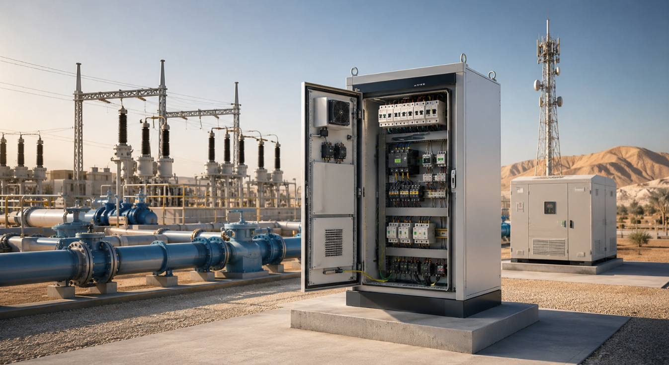
Electronic systems used in Middle East infrastructure are exposed to a combination of electrical and environmental stress conditions. Power distribution equipment, pump control panels, solar inverters, UPS systems, oil and gas instrumentation, industrial controllers, and communication gateways may operate in high ambient temperatures, dusty environments, unstable grid conditions, and long-cable installations.
In these systems, circuit protection is not only used to pass compliance testing. It directly affects equipment uptime, service life, maintenance cost, and field reliability.
YINT Electronics provides circuit protection components for infrastructure equipment manufacturers and system integrators, including TVS diodes, MOV varistors, gas discharge tubes, ESD protection devices, PPTC resettable fuses, NTC thermistors, and EMI suppression components.
1. Electrical Stress in Harsh Infrastructure Environments
Infrastructure electronics often fail when transient energy enters through exposed power lines, outdoor communication cables, sensor wiring, or poorly protected field interfaces. A robust protection design must consider both the electrical threat and the installation environment.
High Ambient Temperature:
Outdoor cabinets and sealed enclosures can experience internal temperatures significantly higher than ambient conditions. Protection devices must be selected with proper power derating, leakage current behavior, and thermal stability in mind. For example, a TVS diodeor MOV that performs well at room temperature may require a higher power rating or larger package when used inside a high-temperature control cabinet.
Grid Surges and Switching Transients:
Remote substations, pumping stations, motor drives, compressors, contactors, relays, and transformers can generate repetitive switching transients. These events may appear on AC inputs, 24 V DC rails, relay outputs, and control signals.
Lightning-Induced Surge:
Long outdoor cables and exposed power lines can pick up high-energy surge pulses. Primary protection devices such as MOVs and GDTs are typically used at system entry points to divert surge energy before it reaches sensitive circuits.
ESD and Dry Environments:
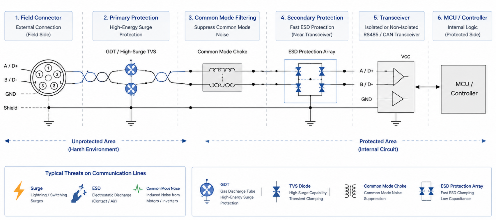
Dry air, dust, maintenance access, HMI panels, communication connectors, and field service operations increase the risk of electrostatic discharge. Low-capacitance ESD protection is especially important for USB, Ethernet, CAN, RS485, display, and sensor interfaces.
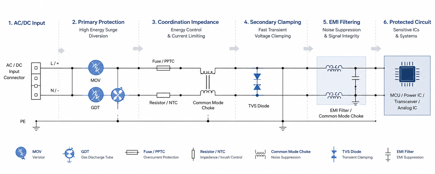
2. Multi-Stage Protection Architecture
Multi-Stage Protection Architecture
For severe-environment infrastructure equipment, a single protection component is rarely sufficient. A coordinated multi-stage architecture is recommended.
Typical protection path:
Outdoor Surge / ESD / Switching Transient
- Primary Protection
- Coordination Impedance
- Secondary Clamping
- EMI Filtering
- Protected IC / MCU / Transceiver
Stage 1: Primary Surge Protection
Primary protection is placed at the point where external energy enters the system.
The purpose of this stage is to divert high-energy surge current and reduce the energy level passed to downstream circuits.
Stage 2: Coordination and Current Limiting
Coordination elements help distribute surge energy between primary and secondary protection devices.
Without proper coordination, the secondary protection device may absorb excessive energy and fail prematurely.
Stage 3: Secondary Clamping
Secondary protection is placed close to sensitive semiconductor devices.
The purpose of this stage is to clamp the remaining transient voltage below the safe operating limit of ICs, transceivers, ADCs, power management devices, and microcontrollers.
Stage 4: EMI Suppression
Infrastructure systems often operate near motors, inverters, switching power supplies, and long cable harnesses. EMI components help reduce conducted noise and improve system stability.
Typical components:Common mode chokes,EMI filters
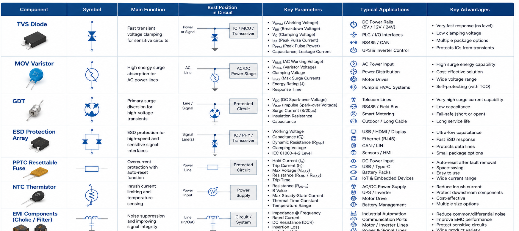
3. Protection Component Selection Guide
Protection devices should not be selected by voltage rating alone. Engineers should evaluate clamping voltage, surge current capability, leakage current, capacitance, temperature derating, package size, and coordination with other protection stages.
|
Component
|
Key Parameters
|
Typical Role
|
Common Infrastructure Use
|
|
|
VRWM, VBR, VC, IPP, PPPM, leakage current
|
Fast secondary clamping
|
DC rails, PLC I/O, UPS control, BMS, communication circuits
|
|
|
VRMS, varistor voltage, clamping voltage, surge current, energy rating
|
High-energy AC surge absorption
|
AC panels, pump systems,
inverters, power distribution
|
|
|
DC spark-over voltage, impulse spark-over voltage, surge current, insulation resistanc
|
Primary surge diversion
|
Outdoor communication lines, smart meters, telecom, long cable interfaces
|
|
|
Working voltage, capacitance, dynamic resistance, clamping
voltage
|
Fast ESD protection for signal ports
|
USB, Ethernet, CAN, RS485, HMI, sensor interfaces
|
|
|
Hold current, trip current, resistance, max voltage
|
Resettable overcurrent protection
|
DC inputs, communication ports, sensor lines
|
|
|
Resistance, B value, rated current, thermal time constan
|
Inrush current limiting and temperature sensing
|
UPS, power supplies, motor drives, battery systems
|
|
|
Impedance, rated current, DCR, frequency response
|
Conducted noise suppression
|
Industrial communication, power input, inverter and control systems
|
Component Selection Matrix
4. Application-Specific Protection Solutions
4.1 Power Grid and Smart Metering
Power grid equipment is exposed to lightning surge, switching transients, grid fluctuation, and electromagnetic noise.
Typical protection design:
- AC input: MOV + fuse or thermal protection
- Outdoor signal line: GDT + TVS coordination
- Communication interface: TVS or ESD array for RS485 / Modbus
- DC auxiliary rail: TVS diode for transient clamping
- EMI path: Common mode choke for conducted noise suppression
Typical applications: Switchgear, Distribution cabinets, Smart meters, Relay protection devices, Power monitoring equipment
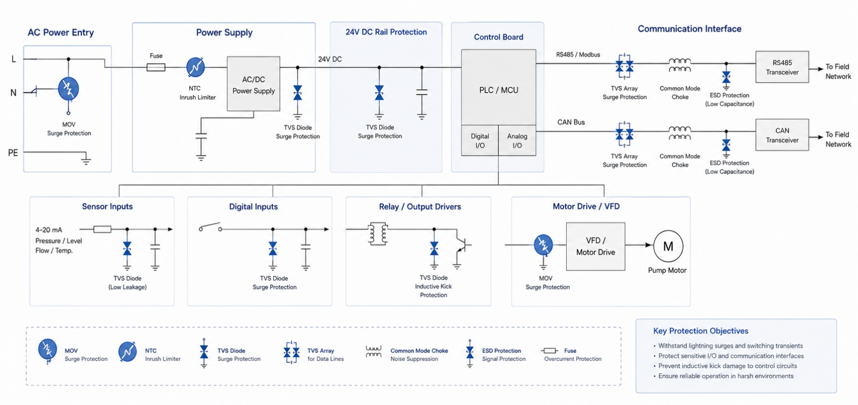
4.2 Pump Control and Water Treatment Systems
Pump control systems often include AC power input, VFDs, 24 V DC rails, PLCs, sensor inputs, and RS485/CAN communication lines.
Typical protection design:
- AC input: MOV varistor for surge absorption
- Power supply input: NTC thermistor for inrush current limiting
- 24 V DC rail: TVS diode for transient suppression
- Sensor input: Low-leakage TVS protection
- RS485/CAN: TVS array + common mode choke
- Overcurrent path: PPTC resettable fuse where automatic recovery is required
Typical applications: Pump control cabinets, Water treatment systems, Remote telemetry units, Flow meters, Pressure sensors
Pump Control / Water Treatment Protection Diagram
4.3 UPS and Backup Power Systems
UPS and emergency power systems require protection across AC input, DC bus, battery interface, control board, and communication ports.
Typical protection design:
- AC input: MOV + fuse protection
- DC bus: High-power TVS diode or suitable surge suppression network
- Battery interface: PPTC or fuse coordination
- Startup stage: NTC thermistor for inrush current limiting
- Communication port: Low-capacitance ESD protection
Typical applications: ndustrial UPS, Telecom backup power, Emergency power cabin, Battery energy storage systems, Inverter control boards
4.4 Solar Inverters and Renewable Energy Equipment
Solar and energy storage systems in desert environments face high temperature, outdoor exposure, DC-side transients, AC-side surge, and EMI noise.
Typical protection design:
- PV input: Surge-rated protection device based on system voltage
- Inverter AC side: MOV varistor for line surge protection
- Communication interface: ESD protection for RS485, CAN, Ethernet
- EMI path: Common mode choke for conducted noise reduction
Typical applications: Solar inverters, PV combiner boxes, Hybrid energy systems, BESS control boards, DC charging systems
4.5 Industrial Automation and Communication Interfaces
Industrial automation systems depend on reliable communication between controllers, sensors, HMIs, gateways, and remote I/O modules.
Typical protection design:
- RS485/CAN connector: TVS array close to the connector
- Long outdoor cable: GDT or higher-surge primary stage
- Signal path: Common mode choke for noise suppression
- MCU side: Secondary ESD or TVS protection
- Power rail: TVS diode + PPTC fuse
Typical applications: PLC system, Remote I/O modules, Industrial gateways, HMI panels, Sensor networks, Oil and gas instrumentation
RS485 / CAN Interface Surge & ESD Protection
5. PCB Layout Rules for Surge and ESD Protection
Component selection is only part of the design. Layout has a direct impact on clamping performance.
Key layout principles:
- Place protection devices close to the connector or transient entry point
- Keep surge current paths short and wide
- Minimize loop area and parasitic inductance
- Avoid routing sensitive signals through the surge discharge path
- Use a low-impedance ground return
- Separate unprotected and protected circuit areas
- For high-speed signals, select low-capacitance devices and maintain controlled impedance
- Coordinate primary and secondary protection stages with adequate impedance between them
A poor layout can increase effective clamping voltage even when the selected protection device has a suitable datasheet rating.
6. Why YINT Electronics
YINT Electronics supports circuit protection design for infrastructure and industrial electronics applications.
Our product portfolio includes: TVS diodes, MOV varistors, Gas discharge tubes, ESD protection devices PPTC resettable fuses, NTC thermistors, Common mode chokes and EMI components
We support customers with:
- Component selection
- Cross-reference
- replacement
- Application-based recommendations
- Datasheet review
- Sample support
- Schematic discussion
- Surge, ESD, and EMC-oriented design guidance
- Stable production and export supply
Request Engineering Support
To recommend the right protection solution, please provide:
- Operating voltage
- Interface type
- Expected surge or ESD test level
- Maximum enclosure temperature
- Signal speed or data rate Circuit diagram if available Target package size
- Annual or project quantity
YINT Electronics can help you select suitable protection components for infrastructure equipment operating in severe electrical and environmental conditions.
Contact YINT Electronics Engineering Team to discuss your application.

 Global


 Hot News


 沪公网安备31011702889749号

